
Inductance, Impedance and Losses
The article explains basic definition of inductance, impedance and inductive losses.
Inductance L
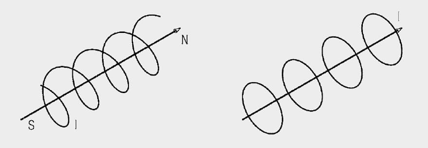
Not only magnetic materials possess a magnetic field, every current carrying conductor creates a magnetic field itself.
Energy can be temporarily stored in the magnetic field. This effect is technically exploited in coils, consisting of one or more wire windings. The synonymous term “inductor” has become established.
There are various types of inductors or coils:
- Air coils (without ferrite material)
- Choke coils with iron powder core or ferrite core
- Toroidal core coil
- Rod core coil
- SMD types are becoming increasingly important as a result of their small size. Besides wound SMD inductors, multiplayer inductors are becoming increasingly established.
All coils share a special behavior described in more detail by the following definitions.
Definition of Inductance L
A circuit element which responds to a current change with a counter-voltage, shows inductive properties. An inductor is a passive component, which, as an AC resistance, produces a counter-voltage, the self-induction voltage.
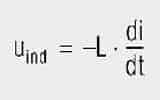
The self-induction voltage (Uind) at the terminals of the inductor is dependent on the rate of current change (di/dt) and a constant of proportionality, the inductance (L):
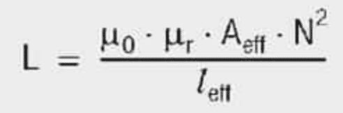
The inductance (L) of the coil is dependent on the core material, the geometry of the core material, the winding turns and the type of windings. The following equation applies generally for calculating an inductance (L):
The unit of inductance (L) is the Henry (H) = Vs/A
The inductance of cores with an inserted air gap can be calculated on the basis of the following formula:
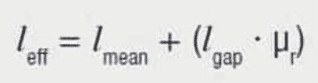
lmean = mean magnetic path length in the core (without air gap)
lgap = path length of the air gap(s)
μr = relative permeability
This formula inserted in formula for general inductance calculation produces:
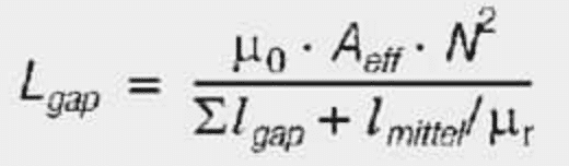
This also allows an air gap width to be determined if the required inductance L and the other parameters are known. Here it must be borne in mind that the above formula only applies if μr is large and the air gap length is much smaller than the mean length in the core.
In order to include stray effects and their effect on inductance, McLyman proposes the following form of calculation for stray effects F:
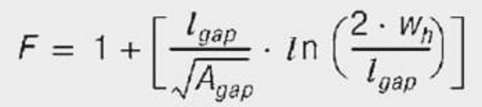
wh = height of the winding
lgap = path length of the air gap(s)
Agap = cross-sectional area of the air gap
F = stray factor
The result is that the inductance LF changes by the calculated value Lgap times the stray factor F:
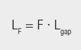
The positive influence of the air gap is an increased saturation current for the same core size. A disadvantage is that to attain a given L value, the number of turns now has to be raised and so, if no winding space is available, for thicker or more than one wire in a bifilar of trifilar winding, the DC resistance of the winding also increases.
Under no circumstances should the number of turns be reduced to compensate the stray effect – this additionally increases the induction and can lead to premature saturation.
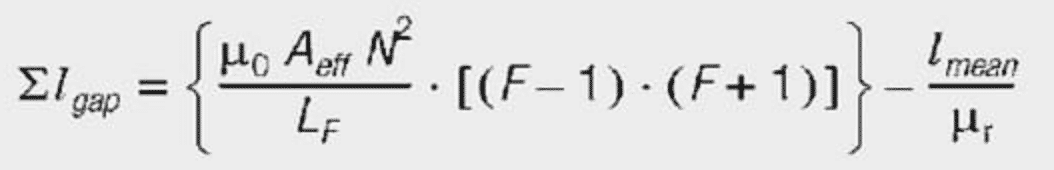
The required air gap width for a given inductance L, taking into consideration the stray factor F, can be calculated to a first approximation as follows:
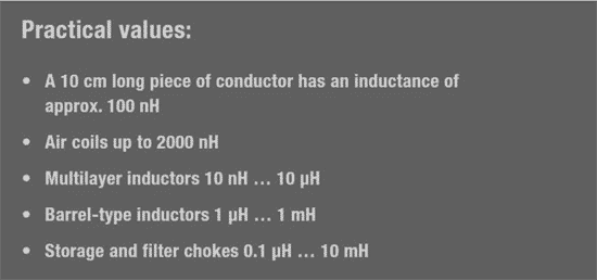
Typical inductance range of various inductor designs – see Table 1.
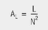
Definition of the AL value
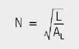
To save the user from calculating the effective magnetic length (leff) and area (Aeff), the corresponding AL value is given for toroidal cores and sleeves. This represents the effective inductance for one winding and must be multiplied by the square of the winding turns (N) to give the actual inductance (L) – see eq.[8].
The (AL) value is the inductance (L) assuming the winding turns N = 1. Thus, given the AL value, the required number of coil windings can be found without having to take the long route of considering the core’s geometric data. see eq. [9]
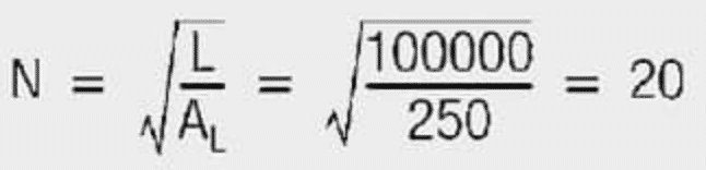
Example:
Required inductance 100 μH; the core has an AL value of 250 nH/N2
Result:
The core must have 20 windings to generate an inductance of 100 μH.
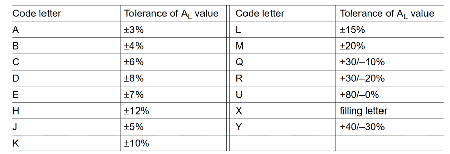
Tolerance code letters
The tolerances of the AL are coded by the letters in the third block of the ordering code in conformity with IEC 62358. The tolerance values available are given in the individual manufacturer’s data sheets and it is usually part of the ordering code.
Impedance Z
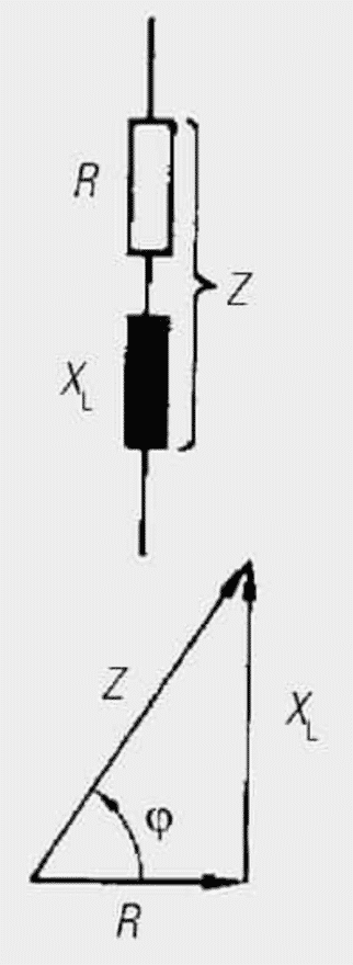
If an inductor is operated with AC voltage, it is clear that it represents a different resistance than in DC operation. The resistance for an AC voltage applied to the terminals of the coil is called impedance (Z).
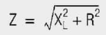
The impedance (Z) is frequency dependent and is composed of the geometric sum of the loss resistance (R) and the reactance (XL) of the ideal coil (L).
The reactance XL is defined as follows:

Observation:
Impedance rises with increased frequency. This linear relationship continues to infinitely high frequencies for an ideal coil.

However, as a consequence of the frequency dependence of permeability and the construction of the coil and parasitic capacitance, the applicability of coils at high frequencies is limited. The impedance declines rapidly from the self-resonant frequency; the inductive nature of the coil disappears.
Self-Resonant Frequency (SFR)
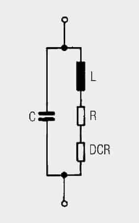
Every inductor also has capacitive coupling arising from its windings or multilayers. These parasitic capacities are symbolized by a capacitor (C) in the equivalent circuit. This condenser in the coil forms a parallel resonant circuit with the inductance.
At the self-resonant frequency, the input energy oscillates back and forth between the elements of inductance and capacitance. No more external energy is absorbed (ideal coil).
If a coil is operated above its resonance, it becomes ever more capacitive. In practice, coils should be operated well below their resonant frequency.
R Losses
No active power (heat loss) is dissipated in the reactance XL due to the 90° phase shift between voltage and current. The total coil losses can be combined into the loss resistance (R), which is connected in series with the ideal inductance (L). This results in the equivalent circuit of real inductance (see Figure 4.).
As the losses in R are however frequency dependent, the DC resistance (DCR) is also always defined in the data sheet specifications. This is dependent on the wire material used or the construction type of SMD inductors and is found at room temperature by a simple resistance measurement.
The size of the DC resistance DCR has a direct influence on the increase in temperature of the coil. Prolonged exceeding of the current rating should therefore be avoided. The total losses of the coil consist of both the losses in the DC resistance DCR and the following frequency dependent components:
- The losses in the core material (magnetic hysteresis loss, eddy-current loss)
- Additional losses in the conductor from the skin effect (current displacement at high frequencies)
- Magnetic field losses of the neighboring windings (proximity effect)
- Radiation losses
- Losses from additional magnetic shielding
All these loss components can be combined into a loss resistance (R). This loss resistance is primarily responsible for defining the quality of the inductor. Unfortunately, mathematical determination of the loss resistance R is not possible.
Therefore inductors are usually measured over the entire frequency range with an impedance analyzer. This measurement provides the individual components XL(f), R(f) and Z(f). The quality factor is defined as a quality characteristic of the inductor.
Copper Losses
The copper losses for inductive components are composed of direct current losses and eddy current losses. The direct current losses are calculated with Ohm’s law:
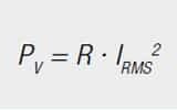
PV = power loss
R = DC resistance
IRMS = effective current
At higher frequencies there are also losses due to the skin effect and the proximity effect. These eddy current losses may be explained directly with Faraday’s law. The current flowing through a conductor generates a magnetic field around this conductor.
This magnetic field changes rapidly as a result of the high frequency, so that a voltage is induced in the conductor and in the neighbouring conductors. This voltage generates a current that opposes the original current. So additional currents are produced in the conductor, as well as in the neighbouring conductors.
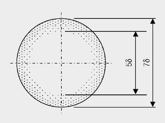
Considering a single conductor, one speaks of the skin effect. For conductors through which high frequency currents flow, current only flows on the outer skin of the conductor (Figure 5.). The penetration depth at which the current density has fallen to a value of 1/e is given by:
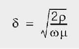
δ = penetration depth
ρ = resistivity
ω = angular frequency 2 πf
μ = permeability of the conductor (for copper μ0)
The penetration depth at 50 Hz is 9.38 mm, at 10 kHz it is 0.66 mm.
The proximity effect plays a far greater role for transformers, whereby neighbouring conductors generate fields displaced by current. A possibility for calculating eddy current losses for simple geometries is described by Dowell. The theory was further developed by Carsten. The mathematical description far exceeds the scope of this post.
It is far more important here to describe the options at hand to limit eddy current losses. Eddy current losses are dependent on the magnitude of the magnetic field. The way to limit eddy current losses is therefore to limit the magnetic field strength.
This can be achieved, for instance, by interleaving the windings, i.e. half of the primary winding is wound, then the secondary winding and thereafter the second half of the primary winding. This reduces the absolute value of the magnetic field and therefore also the eddy current losses. Figure 6. shows an illustration of the H field profile in a copper foil winding with a winding structure primary – secondary and half primary –secondary – half primary.
The magnetic field strength within a winding rises from the inside to the outside, because evermore turns (ever greater currents) are enclosed by field lines. The magnetic field of the secondary winding is opposite to the original field. This again serves to reduce the magnetic field. The reduction in the magnitude of the H field is plain to see.
Thin, flat conductors, e.g. copper foil, can also be used for winding. The thickness should be of the order of the penetration depth. This should only be used for small numbers of turns, because for higher numbers of windings, the large number of layers causes higher eddy current losses.
A further option for reducing eddy currents is to wind with thinner insulated wires rather than a thick wire. Here care must be taken that the single wires connected in parallel have the same current distribution. HF litz wires offer an option here, whereby single wires are twisted with one another so that on average every wire has the same position in the magnetic field. Care must also be taken with this option that the number of layers is not too great.
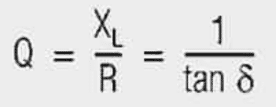
Definition of Quality Factor Q
The component of externally input energy converted into heat in the loss resistance R does not contribute towards the energy stored in the magnetic field. The larger these losses are, the poorer the inductor acts as a buffer.
This defines quality as the quality factor Q as follows:
Practical values:
- Air coil Q up to 400
- Ferrite choke Q up to 150
- SMD multiplayer inductors Q up to 60
The quality-frequency graph on Figure 7. helps select the best inductor construction for the particular application.
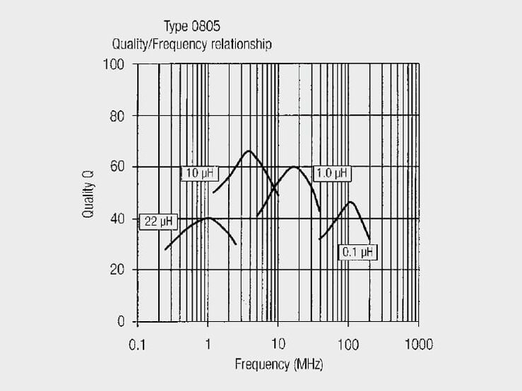
Observations:
- The quality rises to a peak value and then declines.
- Constant small losses in resistance R of the inductor can be assumed up to the peak quality value.
- Beyond the peak value, significant losses become evident, and the inductance also varies on account of non-linearity of the ferrite material.
- The operating range with the smallest losses can be defined up to the quality turning point. If the inductor is used at higher frequencies, the losses increase rapidly.
Temperature Behaviour
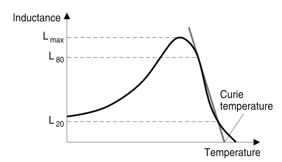
The initial permeability μi as a function of T is given for all materials. Important parameters for a μ(T) curve are the position of the secondary permeability maximum (SPM) and the Curie temperature. Minimum losses occur at the SPM temperature.
Above the Curie temperature TC ferrite materials lose their ferrimagnetic properties, i.e. μi drops to μi = 1. This means that the parallel alignment of the elementary magnets (spontaneous magnetization) is destroyed by increasing thermal activation.
This phenomenon is reversible, i.e. when the temperature is reduced below TC again, the ferrimagnetic properties are restored. The Curie tempertature TC is defined as the cross of the straight line between 80% and 20% of Lmax with the temperature axes (Figure 8).
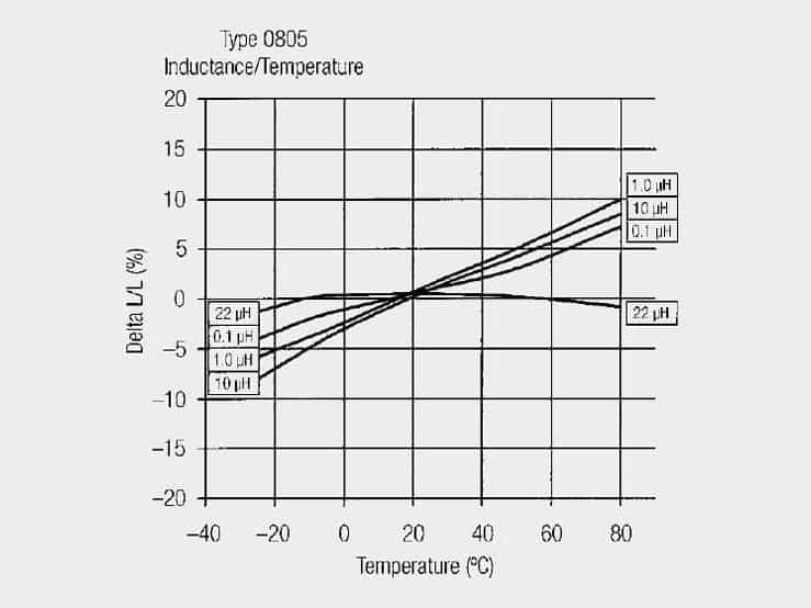
Coils having ferromagnetic core materials show a variable inductive behavior with the ambient temperature. If high demands are placed on the stability of filter circuits constructed with inductors (e.g. in measurement technology), it is expedient to select a coil with an almost linear temperature curve. The inductance change ΔL with respect to the inductance rating L of the coil is lowest in this case.
Figure 9. shows this graph for a 0805 multilayer inductor.
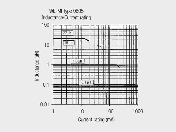
Rated Current
The rated current, which may be carried by an inductor, is defined more precisely by individual component types. The rated current is usually linked with a statement on the self-heating of the component. If the component is operated at its rated current it heats up above the ambient temperature by the temperature stated in the datasheet.
It must then be ascertained if the resulting temperature of the component is suitable for the application. Otherwise a component with a higher rated current loading capacity has to be selected. It has to be checked that by operating at the rated current the part does not exceed the operating temperature (otherwise derating is necessary).
Example:
The maximum current rating value of shielded multilayer inductor is attained if the increase in temperature of the component is greater than 20 °C for the selected test current.
Saturation Current
The saturation current of an inductor is the current at which the inductance value has dropped by a percentage specified in the datasheet.
Example:
Typical storage chokes saturation current specifies the current at which the inductance has dropped by 10%.
Note!
Especially for switching controller applications or applications with high capacitive loads or high inrush currents, the peak current flowing through the inductor can be significantly higher at the moment of switching-on than in regular operation. This may lead to total saturation of the component and therefore to potential consequential faults in the electronics. It is advisable to understand and to limit the current or to activate soft-start functions.