What is an Inductor
This article explains very basic definition of What is magnetism, What is an Inductor ? as passive electronic component and its main application and technologies.
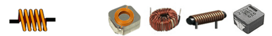
Inductors, also referred to as coils or sometimes choke, are important passive components along with resistors (R) and capacitors (C). Coils usually refer to wound conductive wires, and among them, those with a single wound wire have in recent years particularly been referred to as inductors. If
it is intended for low-frequency applications it usually has a core with a closed magnetic circuit that consists of laminated iron (power frequency) or a ferrite toroid (above 1kHz).
Inductance is usually represented by the symbol “L.” Although this L is said to come from Lenz of “Lenz’s Law” related to electromagnetic induction, there also appear to be various theories.
The basic structure of an inductor consists of a conductive wire wound in a coil shape and is able to convert electric energy to magnetic energy and store it inside the inductor. The storable amount of magnetic energy is determined by the inductance of the inductor and measured in Henry (H).
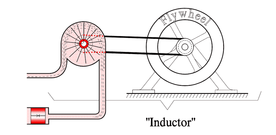
Inductors slow down current surges or spikes by temporarily storing energy in an electro-magnetic field and then releasing it back into the circuit. In hydrodynamic analogy (Fig.1.) inductor works as a large flywheel that offers resistance to every change in the flow/current. Anyone who has turned a bike upside down and turned the wheel up to speed knows, that there is a certain resistance to start. But, as soon as you have gained speed on the wheel it requires very little force to maintain its velocity. If you then want to brake, it requires a considerable force.
Inductor Applications
Inductors are primarily used in electrical power and electronic devices for these major purposes:
- Choking, blocking, attenuating, or filtering/smoothing high frequency noise in electrical circuits
- Storing and transferring energy in power converters (dc-dc or ac-dc)
- Creating tuned oscillators or LC (inductor / capacitor) “tank” circuits
- Impedance matching
- Inductors are also employed in electrical circuits to reduce EMI by attenuating high-frequency noise in order to meet EMC emission and immunity requirements.
What is a choke?
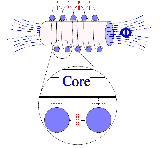
Primarily inductors consist of a coil. If we insert a core of magnetic material the inductive properties of the coil will increase. Such coils are then called chokes. When we draw current through a choke electric currents are induced in the magnetic material that try to create a counteracting magnetic field. These currents are undesired both for that reason and because they create heat losses.
Homogeneous magnetic bodies are excluded; the induced current would be too high. Instead mutually isolated ribbons are used or a powder technology where the binder material between the magnetic granules limits the induced current by their resistivity.
Connection
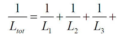
Inductors may be connected in series or in parallel; inductance then comply with the same laws as for resistors.
Connection in series

Connection in parallel
For loss free coils and coils with the same angle of phase applies
Inductive Reactance
Just as a capacitor the inductor presses a reactance on an AC circuit. To divide this reactance from that of a capacitor it is called the inductive reactance, XL. The quantity is expressed in ohms and complies with the formula:
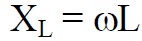
ω = 2 x π x f, where f means the frequency expressed in Hz.
Basic Structure of Inductors and Inductance
The most basic inductors consist of a conductive wire wound in a coil shape, with both ends of the conductive wire as external terminals. In recent years, most inductors include a core, around which a conductive wire is wound.
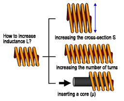
The inductance of an inductor is determined by the following equation [4]:
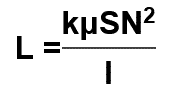
- L Inductance (H)
- k Nagaoka coefficient
- μ Core permeability (H/m)
- N Number of coil turns
- S Coil sectional area (m2)
- l Coil length(m)
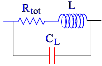
Equivalent Circuit
An inductor can be described with the Figure 2.
The stray capacitances between the windings and between windings and core can be summarized to one single total capacitance CL. The winding wire also has resistance and in the magnetic material equivalent loss resistances appear. Taken together the characteristics of the inductor can be described with following equivalent circuit.
At lower frequencies the capacitance plays a minor part, but as frequency rises we reach the self resonant frequency, fr, (sometimes abbreviated SRF) where the impedance curve arrives at a peak and then turns downwards and becomes capacitive.

The measurement frequency (test frequency) is at a sufficient distance from fr and always is stated for respective inductor.
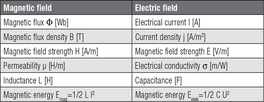
Electric vs Magnetic Field
Comparing magnetic fields with electrical fields, analogies emerge between certain parameters. These are summarized in Table 1.: