Film Resistors
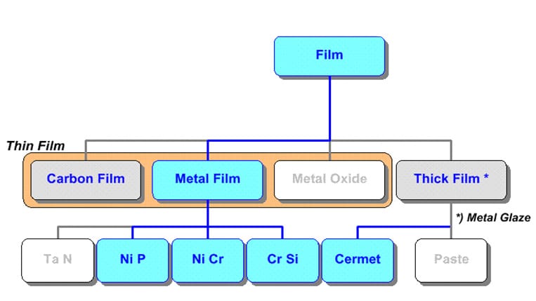
Non-wirewound resistive elements may be produced and arranged in a lot of different ways. We shall present the following types, differentiated by constructional material or specific design:
R 3.3 Metal film / thin film
R 3.4 Metal foil
R 3.5 Metal glaze/thick film
R 3.6 Metal oxide /”metox”
R 3.7 Carbon film
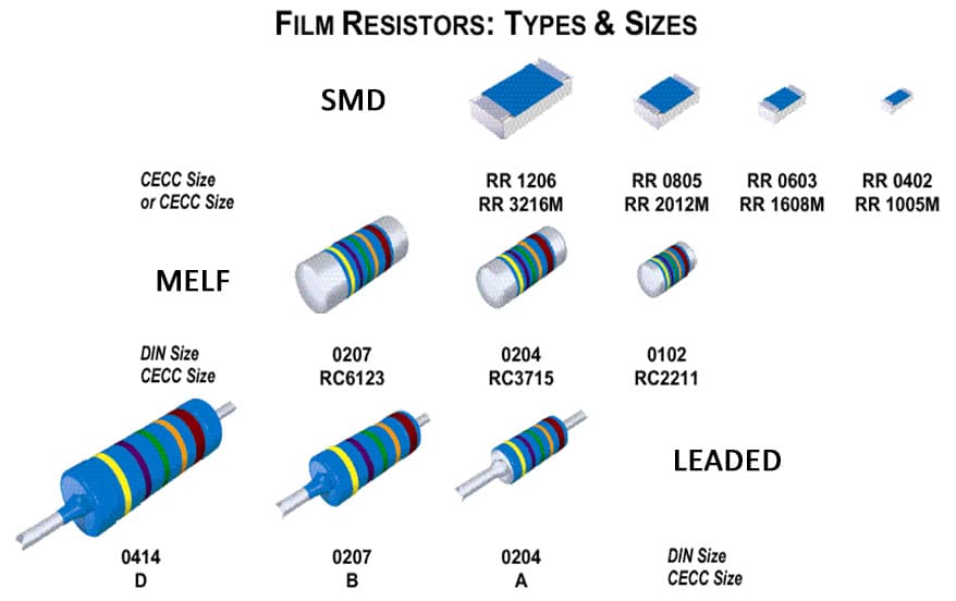
Film Resistors Packaging Types
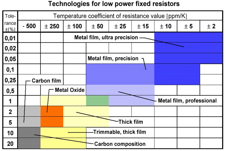
Low Power Resistor Selection Guide
R 3.2 INTRODUCTION TO FILM RESISTORS
Film resistors are built either on cylindrical rods or on planar substrates. Usually the material in the rods and substrates is ceramic in the state of aluminum oxide (alumina), but glass may occur. Hollow cores exist but are more and more abandoned when sizes are becoming smaller. This design suffers also from drawbacks: the construction is more fragile and the heat dissipation is poorer than that of a solid core.
R 3.2.1 Hole mount
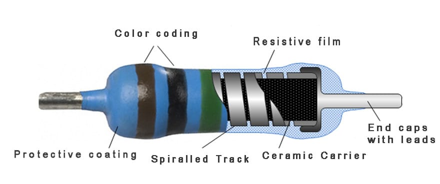
A typical film resistor is shown in Figure R3-1.
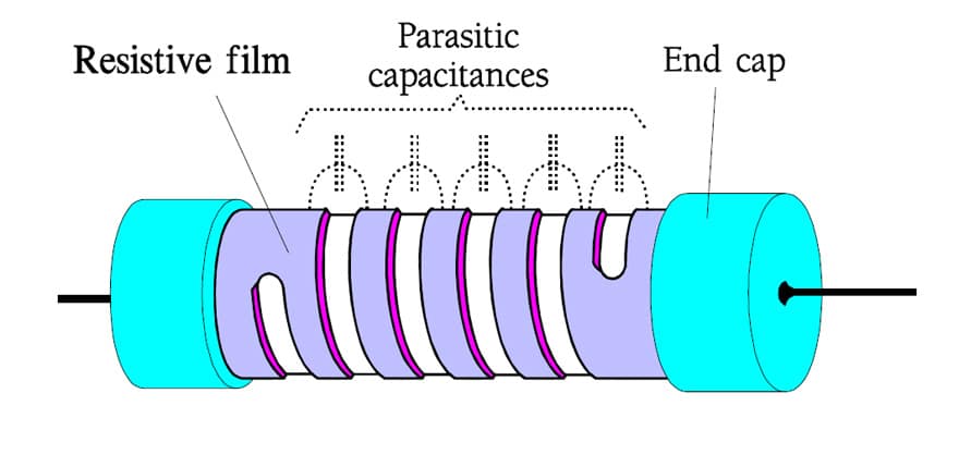
The film of the cylindrical rods thus are cut in a helical track to a long path, usually with a laser. A more stylized sketch is shown in Figure R3-2. The pitch of the helix track can be varied in order to increase the resistance of the film. For thick films an increase of up to 150 times, for carbon and metal films up to 1000 times or even more.
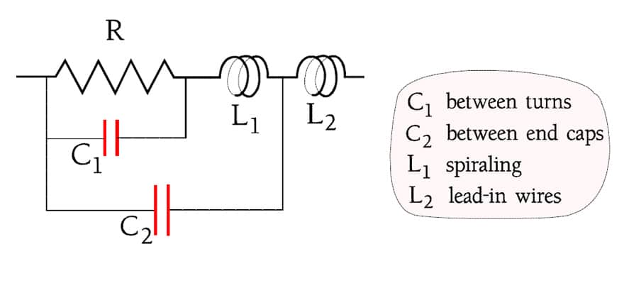
As indicated in the figure a stray capacitance is developed between the turns. Because the turns also constitute a coil the resistor will get a certain inductance. All in all the spiraling produces a frequency dependent impedance where the capacitance is dominating. The conditions are illustrated by the Figures R1-15, R1-16 and R3-3.
Film resistors may be approximately classified as follows:
- values < 100Ω are inductive.
- values between 100Ω and 470Ω are practically true resistive
- values above 470Ω are capacitive.
Fusible and flameproof resistors
A strong overload of carbon and metal film resistors will lead rapidly to an open circuit that in most cases is accompanied by a build-up of smoke, glow or even fire. Some manufacturers have developed designs that burn off within certain limits. They are called fusible resistors. The open-circuit conditions are defined in particular power-time diagrams. The limits still must be regarded as “broad”.
If coatings and casings are used that don’t generate or sustain a fire, we talk about flameproof resistors. The drawback with these casings in past was partly an impaired environmental protection and partly a troublesome environmental disadvantage from a recycling viewpoint, since they often contain bromine compounds. The modern flameproof resistors has replaced the bromine based fire retardants by a metal oxide compounds. Check with manufacturer datasheets.
Chips and networks
Film resistors also exist as discrete chips or in so called resistor networks where they are collected under a common housing. We will deal with these components in next lessons.
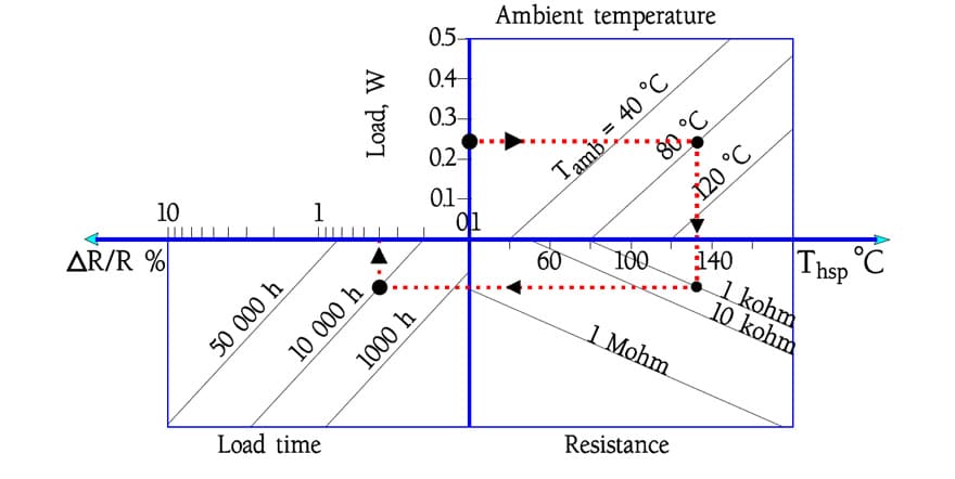
R 3.2.2 Load chart Nomogram
The connection between stability, operating time, temperature, power and resistance usually are shown in particular nomographic load charts. Figure R3-4 shows such a diagram for a sample film resistor. The example reveals how an 1 kΩ resistor working with 0.24 W at an ambient temperature of 80 °C gets a Hot Spot temperature of approximately 137 °C which after 10 000 hours operation produces an expected resistance change of approximately 0.4%. Such a modest change indicates a considerable derating of the nominal power that very well could have been 0.4 or 0.5 W in this example.
Consequently a nomographic load diagram corresponds only to one type and size (power).
In the nomograph example below you shall start at the actual power on the load axes and draw a horizontal line to the right to the parameter of actual ambient temperature. From that point of intersection you draw a perpendicular line that crosses the axis for actual Hot Spot temperature, and continue to the parameter of actual resistance. There you continue horizontally to the parameter of estimated time of operation. From this point of intersection you then continue 90° upwards to the axes marked with the corresponding calculated resistance change.