
Potentiometer Types
R 4.2.1 Power potentiometers

Power potentiometers are as a rule wirewound. They are wound on a ceramic body and lack, due to heat dissipation concerns, encapsulation in casings or housings. Often they have a touch protection of silicone lacquer, cement or enamel and they are readily used as rheostats. If we turn the shaft of a rheostat towards zero resistance it is not unusual that the current burns off the last turns in the winding if the load impedance is low. Hence, the current in a rheostat must not exceed that of the rated power.
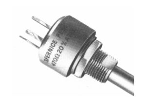
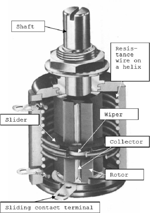
The sliding contact of the wiper sometimes consists of silver. If there are sulfur compounds in the air, for example from oil incineration plants, silver sulfides are formed on the sliding contact. If they are not worn off by frequently recurrent adjustments, the next change of position will cause ESR values going towards open circuit modes. A typical example of a power potentiometer is shown in Figure R4-28.
R 4.2.2 Panel mount potentiometers Type 2
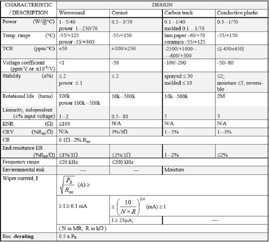
Under this heading are collected wirewounds with bobbins of fiber card or the like and non-wirewounds with resistance elements of molded carbon composition, conductive plastic or cermet applied on substrates of laminated paper (bakelite paper), plastic or ceramics. In order to prevent the potentiometer housing from separating when the shaft is turned, the housing or mounting plate is supplied with an anti-rotation pin that fits in a corresponding hole in the panel.
The most simple carbon potentiometers have a sprayed and dried carbon compound on bakelite paper. After a number of cycles they will meet with contact disturbance (noise) due to wear grooves in the track and wear debris around the wiper. The best rotational life is with the conductive plastic potentiometer. Due to the metal particles in the cermet it develops an abrasive action that wears on the wiper. Therefore the track is often lubricated with a grease of some kind which reduces the wear.
Usually the potentiometers are encapsulated, for more severe environments “hermetically”, which here means seal rings around the shaft. A smaller degree of sealing is offered by the so called “dust-proof” ones. Surface Mount potentiometers exist, both with and without encapsulation. If the assembly process involves washing, the design at least must be tight against rinsing fluids. Otherwise rinsing products like flux residues may be deposited on the track which can lead to severe contact disturbances.
A phenomenon that threatens components with cavities, if they are subjected to temperature changes in humid environments, is the so called pumping effect. An insufficiently sealed potentiometer with large cavities inside the housing is particularly subject to this phenomenon. If humid air in the cavities is cooled the water vapor will condense and create a negative pressure in the cavity at the next temperature rise.
New humid air is sucked in, etc. Instead of having such a half-tight potentiometer, a hole in the bottom of it would be better, so that condensed water could run out…Thus, use qualitatively sealed potentiometers if the environment requires. Especially those with a carbon track, conductive plastic or wire winding are sensitive to moisture. A special type of carbon track potentiometer is the slider pot with a linear motion. It is usually used in audio controls in studio mixer panels.
It is important that the bulk track is molded and thus relatively wear resistant, partly to allow long use, and, partly so that noise producing wear will be prevented. Caution! If one has chosen some type of slider potentiometer it is usually difficult to find any equivalent second source.
Current derating
The current through the wiper should in potentiometers with a carbon or conductive plastic track be kept low in order to minimize noise and wear, preferably values less than 0.25 mA. Wirewound potentiometers, on the other hand, should draw a certain minimum current through the wiper – more than 0.1 mA – in order to reduce noise and contact disturbances. The contact resistance in cermet potentiometers has the sensitivity of the metals to small currents and should likewise carry a certain minimum current. An adequate minimum value might be 25 µA (Reference to Figure R6-15). The data sheets also state a certain maximum current through the wiper, for example, 100 mA at resistances below 100 ohms. At higher resistance values the contact resistance CR increases, which could lead to local overheating if the wiper current is not kept down.
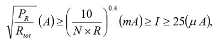
Thus, the wiper current is determined not only by the resistance value but also by nominal power, resistance track material and rotational life (number of shaft turns). In the summary tables we shall describe some guiding formulas for the wiper current I that is confined within certain limits. The highest limit is the maximum power current of the potentiometer, that may be calculated from the equation.

Next maximum limit – that never must be greater than the maximum power current – is calculated by means of a formula that contains the rotational life N expressed in number of million shaft revolutions (megarevolutions, “MR”) and the resistance in question expressed in kohms. The result is obtained in mA.

Finally there exists a commonly recommended minimum limit. Example. Suppose a cermet potentiometer with PR = 0.5 W, N = 100 000 revolutions = 0.1 MR, R = 1 MΩ = 1000 kΩ and the minimum limit for cermet = 25 µA. If we insert 0.1 and 1000 respectively in the applicable formula
we obtain 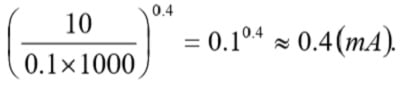
This value is well below the absolute maximum current derived from 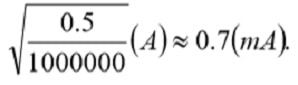
Thus the wiper current should be adjusted to lie between 0.4 mA and 25 µA.

Precision potentiometers, type 1
According to IEC precision potentiometers are classified as Type 1. They exist in both bushing mount styles and in servo applications. In the latter case high demands are made for rotational life and low torque. Such potentiometers are supplied with ball bearings. If they in addition are sealed against moisture this will influence the torque. The solution of such problems implies explicit requirement specifications and close cooperation with prospective manufacturers. For very severe environments there exist, among other things, oil-filled potentiometers.
R 4.3.1 Wirewound, Type 1
Wiper current Resistance elements formed from metal always form oxides on the surface that the wiper has to break through in order to establish electrical contact. The break through may be carried out by movement wear and by means of electrical voltage. If the potentiometer operates at dry circuit conditions, i.e., 10⋅⋅⋅30 mV and wiper currents less than 10 µA, this will make the contact more difficult and increase the noise disturbance. The schematic for a cermet potentiometer in Figure R4-15 also is applicable to wirewounds.
The disturbances also increase at decreasing temperatures and seem to be still more pronounced when the temperature is below –30 °C. Thus, the wiper requires a certain current in order to get a noise free operation, preferably more than 0.1 mA. Lubricants In order to reduce the wear and prevent oxidation, both on track and wiper, the track is in most cases lubricated with some kind of grease or oil. Most common are silicone compounds where the viscosity is relatively constant over a broad temperature range. The silicones, however, show a rapidly increasing viscosity when greases reach temperatures below –5⋅⋅⋅ -15 °C and oils below –30⋅⋅⋅ -40 °C. In addition at a moderate wiper speed the wiper tends to slide on top of the lubricant film, causing the ENR values to rise unacceptably. Silicone lubricants have a characteristic that in certain applications may be disastrous to the surroundings: they “creep”.
Their surface tension is so low that the lubricant “wets” adjacent surfaces that are contaminated with a thin film. We talk about a silicone infection. A small dab of grease will within months spread over square meter large areas. The phenomenon causes problems in following ways:
- Contaminated surfaces might be electrically isolated by the lubricant film at dry circuit conditions.
- Contaminated contacts with a breaking function accompanied by arc overs, will be isolated by the silicone granules that are formed when the miniature arcs decompose the silicone film.
- Contaminated lens systems in high energy lasers will have their lens surface damaged by the laser beam when it burns the silicone film.
- Gluing of components on contaminated surfaces is made impossible.
Single-Turn
Figure R4-30 depicts a typical single-turn servo potentiometer. There are precision styles for bushing mount applications and there exist two designs: with and without end-stops. The latter is called continuous which means, an electrical discontinuity occurs when the wiper traverse the non-conductive gap located between the ends of electrical continuity travel. The resistance wire sometimes consists of gold-platinum alloys. They are used where the contact pressure of the wiper has to be low and oxide formations minimized, for example in gyro potentiometers.
Multi-Turn
If we, on a thick isolation lacquered copper wire wind a resistance wire, and bend this “wire bobbin” into a helix we obtain a resistance element for a multi-turn potentiometer, as shown in Figure R4-31. This helical element then is fitted in a housing and connected to terminals. The shaft is supplied with a sleeve with a longitudinal spline and an electrical contact track.
On this rotor a slider then travels that makes contact both with the track and the resistance helix. The slider also is supplied with cams that trace against the inner side of the housing and move the slider along the rotor when shaft is turned. The common number of turns is 3, 5 or 10 but higher numbers exist. The electrical angle is usually defined in multiples of the number of turns. Thus, a 10 turn has the angle 3600°. That means, among other things, that the resolution becomes better and the setting accuracy greater.
4.3.2 Hybrid potentiometers
If the resistance wire of a multi-turn potentiometer is coated with conductive plastic as shown in Figure R4-32 we have a combination element of wire and plastic, a so called hybrid, that makes possible a multi-turn construction with conductive plastic. There are certain benefits with the smooth conductive plastic surface and the current capability of the embedded wire but the construction is, of course, more expensive than that of a conventional multiturn wirewound potentiometer.
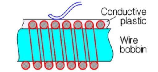
Lubricants on the hybrid track are necessary. Otherwise the track will be worn down after a small fraction of the specified rotational life. The principle for multi-turn constructions as shown in Section 2.3.1 might be applied on conductive plastic (CP) if the lacquer isolated copper wire bobbin is directly coated with CP. Use of this process, however, is quite exceptional.
4.3.3 Non-wirewounds, Type 1
Normally non-wirewound precision potentiometers are manufactured as single-turn devices. Except for conductive plastic cermet is used, as well bushing mount styles, in servo applications. The design from Figure R4-30 could as well be applicable to a nonwirewound servo potentiometer. Just as in servo applications the rotational life has to be high and puts high demands on the wiper design, the contact pressure and the track which therefore has to be polished. The polished CP track allows a number of revolutions of several tens of millions.
Then, however, the wiper current must be limited. Otherwise a kind of welding effects on the contact surfaces along the track results, that will destroy both wiper and surface and increase wear and noise. The wiper current should be limited to maximum of 0.25 mA. Example: A serious manufacturer promised a rotational life of 100 x 106 revolutions at 2 mA. But he recommended a maximum wiper current of 10 µA! The 0.25 mA rule, however, is not unconditional. Material, resistance value, nominal power and the number of revolutions of the rotational life come into play. The wiper current in wirewound and cermet potentiometers should comply with Formula R4-2, while hybrid and conductive plastic potentiometers should have a wiper current, Imax, according to Equation R4-3.

The contact function of cermet potentiometers is in its nature suggestive of that of the metals. Therefore the wiper current should, just as in wirewounds, also be limited in low values. An approximate minimum value might be 25 µA. (Figure R4-15). In the summary tables some guiding formulas are stated.
R 4.3.4 Linear motion potentiometers
A parallel to the slider potentiometer mentioned in section R4.2.2 but in Type 1 design are the linear actuated precision potentiometers or linear position transducers. Thus, they have a straight resistance track and a piston or guide bar that holds the wiper and transforms linear motions. The mechanical travels vary between 10 mm and 1.2 m. The resistance tracks are made of wirewound or hybrid elements, of cermet or conductive plastic. As to other parameters they have the same characteristics and specifications that apply to corresponding rotary potentiometers.
