Metal Glaze Thick Film Resistors
R 3.5 METAL GLAZE / THICK FILM
If we screen print a paste of finely scattered metal particles (for example ruthenium, ruthenium oxide, rhodium, palladium, tantalum-tin) together with glass powder on a ceramic substrate and fire the film until the glass melts, we get a resistive film from some μm up to 25 μm (1 mil) of thickness, a so called thick film or metal glaze. The substrate has to be chosen with great care in order to constitute an integrated part of the melted glass powder. A variant of thick film exists in some potentiometers under the name of cermet. Actually it is a manufacture connected film that first was put on the market by the manufacturer Beckman Industrial. Today the name cermet is generally recognized.
The film is very environment resistant and has surface resistivities up to 1 MΩ/square, which allows high resistance values in small chip sizes. Here the thick film meets with its dominating application together with its existence in networks. Axial through hole mounted components are manufactured almost exclusively as high ohmic/high voltage types. Traditional high ohmic resistors in the 100-MΩ range of carbon composition, carbon film or metal oxide designs generally with advantage can be replaced with metal glaze resistors.
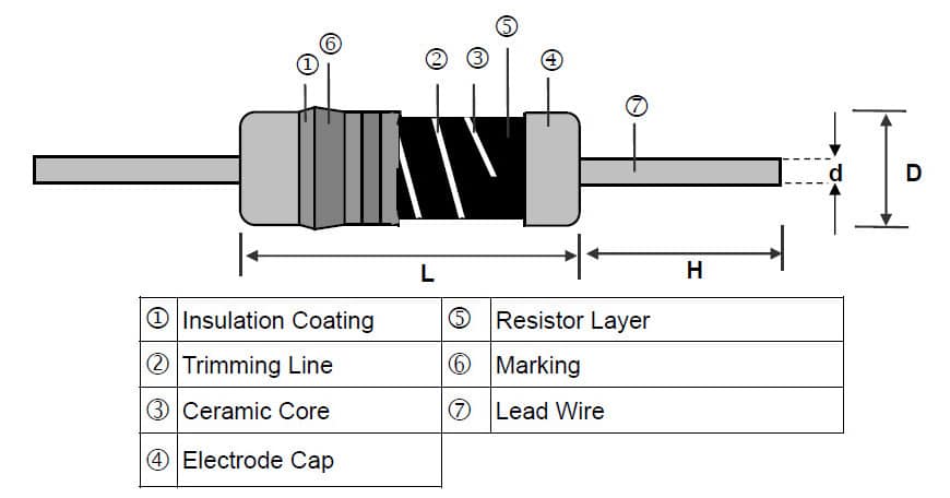
After the firing cylindrical bodys are spiraled as shown in Figure R3-1 and R3-2. Plane surfaces are laser trimmed to exact values. The tolerances usually are situated between 1 and 10 % and the TCRs between ±25 and ±300 ppm/°C. The closest TCR, ±25 ppm, deserves certain caution because of the risk of drift outside the specification limits.
The conduction mechanism in the metal glaze/ thick film consists of contacts between small metal granules. This leads to considerably more noise than in genuine metal film resistors. Furthermore the user should be careful with strong pulse loads, at least in the k range. They might give permanent resistance changes due to damaged contact points.
Another phenomenon that characterizes thick film materials more than pure metals is non-linearity. The thick film with its complicated conduction network and countless contact spots suffers from non-linearity at relatively low resistance values. Following diagrams show the difference between thick film and metal film materials in two SMD styles: a metal film “MELF” and a thick film chip.
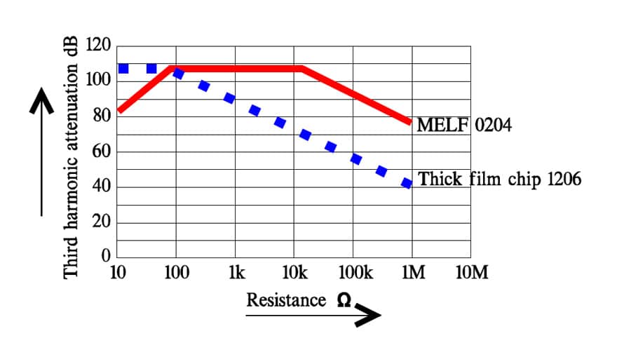
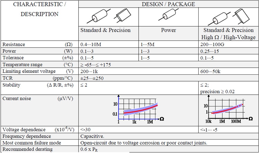
Table R3-2. METAL GLAZE / THICK FILM RESISTORS