Resistor Terms and Definitions
Nominal Resistance
Designed resistance value usually indicated on the resistor.
Power Rating
Maximum allowable power at rated temperature. Some of our chip resistor arrays and networks specify the whole power rating as a package.
Rated Temperature
Maximum ambient temperature at which the power rating may be applied continuously. The rated ambient temperature refers to the temperature around the resistor mounted inside the equipment, not to the air temperature outside the equipment.
Rated Terminal Part Temperature
Maximum terminal part temperature of the surface mount resistor at which the power rating may be applied continuously. Includes the temperature rise by self heat generation.
Derating Curve
Curve that expresses the relation between ambient temperature and the maximum allowable power, which is generally expressed in percentage.
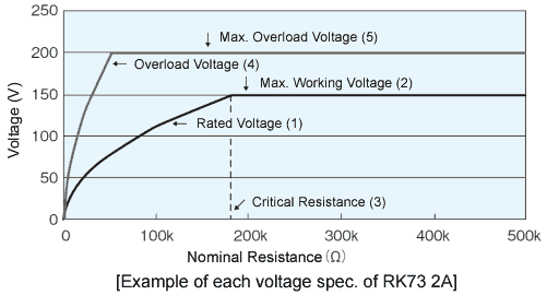
Rated Voltage
Maximum allowable D.C. or A.C. voltage (RMS), capable to be continuously applied to a resistor or a resistor element under the rated ambient temperature or terminal part temperature, which is calculated from the rated power and nominal resistance using the following formula.

Rated voltage shall not exceed the max. working voltage.
Critical Resistance
The maximum nominal resistance value at which the rated power can be applied without exceeding the maximum working voltage. The rated voltage is equal to the max. working voltage at the critical resistance value.
Max. Working Voltage
Maximum D.C. or A.C. voltage (RMS) that can be continuously applied to the terminations of a resistor. However, the maximum value of the applicable voltage is the rated voltage at the critical resistance value or lower.
Maximum working voltage and rated voltage are calculated direct-current voltages based on rated power. Sine wave is assumed for the alternate-current so the peak voltage should be √2 times the maximum working voltage. When the wave form is not a sine wave, or when the resistance value exceeds the critical resistance, please contact manufacturer/consult the product datasheet for the applicable peak voltage.
Overload Voltage
Allowable voltage which is applied in 5 sec. under short time overload test. Overload voltage shall be 2.5 times of rated voltage or max. overload voltage, whichever is lower.
Max. Overload Voltage

Dielectric Withstanding Voltage
A.C. voltage (RMS) that can be applied to a designated spot between the electrode and the outer coating in one minute, in the voltage proof test (JIS C5201-1 4.7).
Temperature Coefficient of Resistance(T.C.R.)
Relative variation of resistance between two given temperatures when temperature is changed by 1K.
