SMD Resistors
Surface Mount (SMD) resistors allow a very large miniaturization. This in its turn means short conduction paths and good high frequency characteristics. Furthermore there are particular high frequency (HF) chips in thin film technique.
Fixed SMD resistors are manufactured in two basic designs:
- rectangular SMD chip
- cylindrical leadless, so called MELF (Metal Electrode Face Bonding).
Mounting / Soldering / Gluing
It is important to remember that SMD components, more than others, are influenced by temperature changes, especially for the larger component. Thus, dimensions and mounting directions are most important. Further, short and wide bodies are preferable to long and thin ones, partly for strength reasons, partly because of the inductance and with that the frequency dependence will decrease. Still another reason is that differences in the coefficient of expansion between substrate and chip decreases in significance with shorter distances between terminations.
The thermal dissipation may push the temperature in the solder joints above the detrimental 110…115 °C temperature range before we attain the nominal power PR. Permissible maximum power of a MELF resistor can be calculated from Equation R3-3:
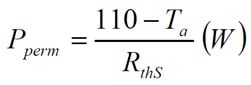
where:
- Ta = ambient temperature in °C
- RthS = thermal resistance of the solder joint, i.e., its temperature rise in K/W
- Pperm = permissible power
Information about thermal resistance of the solder joint of standard components applies to soldering conditions for normalized test board patterns.
Solderability is vital for a successful result. The user should use a wetting balance and international standard requirements at inspection. The end caps of MELFs sometimes have been difficult to solder. Metal glaze MELFs with metallized terminations generally have a better solderability.
SMD Cross over chips / “Jumpers”
Sometimes it’s necessary to complete existing application of printed circuits by separate short-circuiting between two points. Particular components are used, so called cross overs, cross conductors or jumpers, with the lowest possible resistance.
They exist both as rectangular thick film chips as well as metal film MELFs. Max resistance for the thick film chips usually is ≤50 mΩ at sizes between 0603 and 2010. Thin film MELFs in typical sizes of L x D ≈ 2 x 1.4 to 6 x 2.4 mm are specified for ≤10 mΩ.
As well as maximum resistance a maximum current is also specified for these components.
Failure modes
The weakest point of an SMD is the terminations and solder joints that break after sufficient temperature changes. Good components should stand at least 100 cycles between temperature limits. Applications like modern car electronics have forced the requirements up to some 1000…10 000 temperature cycles.
Except for failures resulting from open mode in connections and solder joints there always are failure modes typical for corresponding hole mount types.
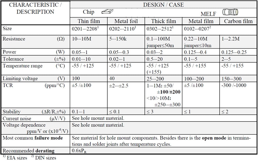
Table R3-7. SMD: CHIP & MELF