Noise and Corrosion
R 1.9 NOISE
R 1.9.1 Definition
Noise manifests itself as a spontaneously fluctuating voltage whose instantaneous amplitude is randomly distributed. The instantaneous value is both unpredictable and of minor interest except in certain critical applications. Instead, one measures a time-averaged value. It consists of the root of the mean-square value of voltage transmitted in a particular frequency pass band.
The noise consists of two components: Thermal noise and current noise.
R 1.9.2 Thermal noise voltage
Thermally agitated charges in the resistance track cause a randomly varying voltage that is called thermal noise. It may be described as the root mean square voltage, E, according to the formula
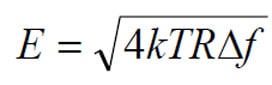
,where:
- k is Boltzmann’s constant 1.38 x 10⁻²³ Ws/K
- T is the absolute temperature in Kelvin (K)
- R is the resistance value in ohms
- Δf is the band width of the detector system in Hz.
From this formula we see that the thermal noise is independent of what kind of resistor type (style) we use.
R 1.9.3 Current noise voltage
If we record a DC current through an electrical conductor we would at a sufficiently high amplification be able to see small randomly occurring ripples on the “surface”. They manifest themselves as an increase in mean-square voltage over that caused by thermal noise. The contribution is called current noise or often only noise. It appears above all in materials whose resistance is produced by means of joints between conductive particles embedded in an isolator compound. It is suggestive of the coal granules in the early carbon microphones. In the contact spots current area and conductivity are changed greatly which in turn generates current noise. But also in pure metals in wires and films current noise is generated, although values are negligible in most cases.
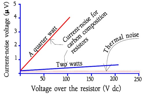
The current noise is approximately direct proportional to applied voltage and inversely proportional to frequency (Figure R1-14).
Above 10 kHz it usually can be neglected. It grows with the width of the pass band over which it is integrated. It means that the pass band 100…..1000 Hz approximately has the same contents of noise that the pass band 1…..10 kHz. Or in general, every frequency decade has approximately the same noise contents. Suppose the noise contents in a particular defined frequency decade is 1 mV/V. Then the noise for 100 Hz…..10 kHz would be √(12+12) = √2 ≈ 1.4μV/V.
Since current noise above 10 kHz is often negligible earlier measurements covered the frequency range 200 to 10 kHz.
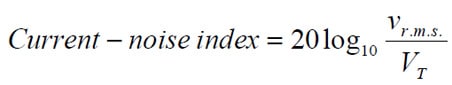
According to IEC 195, DIN 44 049, part 1 and MIL-STD-202, method 308, one takes the typical noise characteristic of a frequency decade as one’s starting-point and measures a so called current-noise index expressed either in mV/V or in dB, per frequency decade. One measures geometrically around 1000 Hz, which gives the frequency decade 618 to 1618 Hz. If vrms is the number of mV current noise in an open circuit and VT the applied DC voltage we obtain:
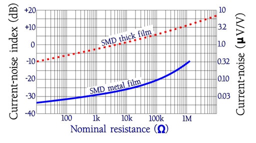
In Figure R1-15 we show examples of accounts of noise curves for two different resistor materials. Note how the noise grows with resistance value.
Current noise can be of great importance in the following cases:
- High resistance value.
- High DC voltage applied.
- Low level circuits and high amplification.
- Low or no negative feed back.
- Acoustic frequency range.
- Linear circuit functions.
R 1.10 AQUEOUS ELECTRICAL CORROSION / ELECTROLYSIS
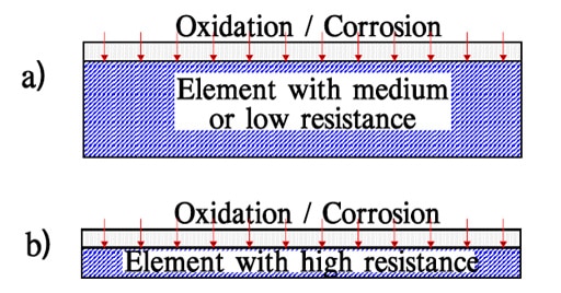
Resistance is in principle based on slender conduction paths that are thinner the higher the resistance is. As shown in Figure R1-16 high ohmic resistors become in that way extremely sensitive to electrolytic corrosion.
Corrosion in its turn implies the presence of moisture. Encapsulation and tight encasing will be decisive in providing environmental resistance of the component. Moreover, if the resistor is loaded with a DC voltage the corrosion velocity increases with voltage until internal heating dries the points of attack.
Many people may experience water electrolyzation in science emperic during the school days. Insert platinum electrode into water where electrolyte is included and turn electricity so oxgen evolves from the anode and hydrogen from the cathode. Similar phenomenon happens inside of a resistor. If you continue to use resistor of which the coating inside has been infiltrated by air containing moisture or water, resistive body turns into ion and melt out instead of generating oxygen at the anode side. Resistive body disappears finally leading to disconnection.
This phenomenon is called electric corrosion because the resistive body seems to be erroded by electricity whereas the disconnection caused by electric corrosion is called disconnection by electric corrosion. The higher the resistance is, the more electric corrosion is likely to happen. This is because the resistive body with high resistance has thin film and narrow pattern, which is easier for the resistive body to be melted in short time. Eletric corrosion occurs mainly for carbon film or metal film type resistors. To avoid this, wash the resistor after soldering to remove the electrolyte as well as seal the resistor excluding moisture. If there should be no characteristic problem, you can replace it by metal glaze film resistors which can hardly turn into ion.