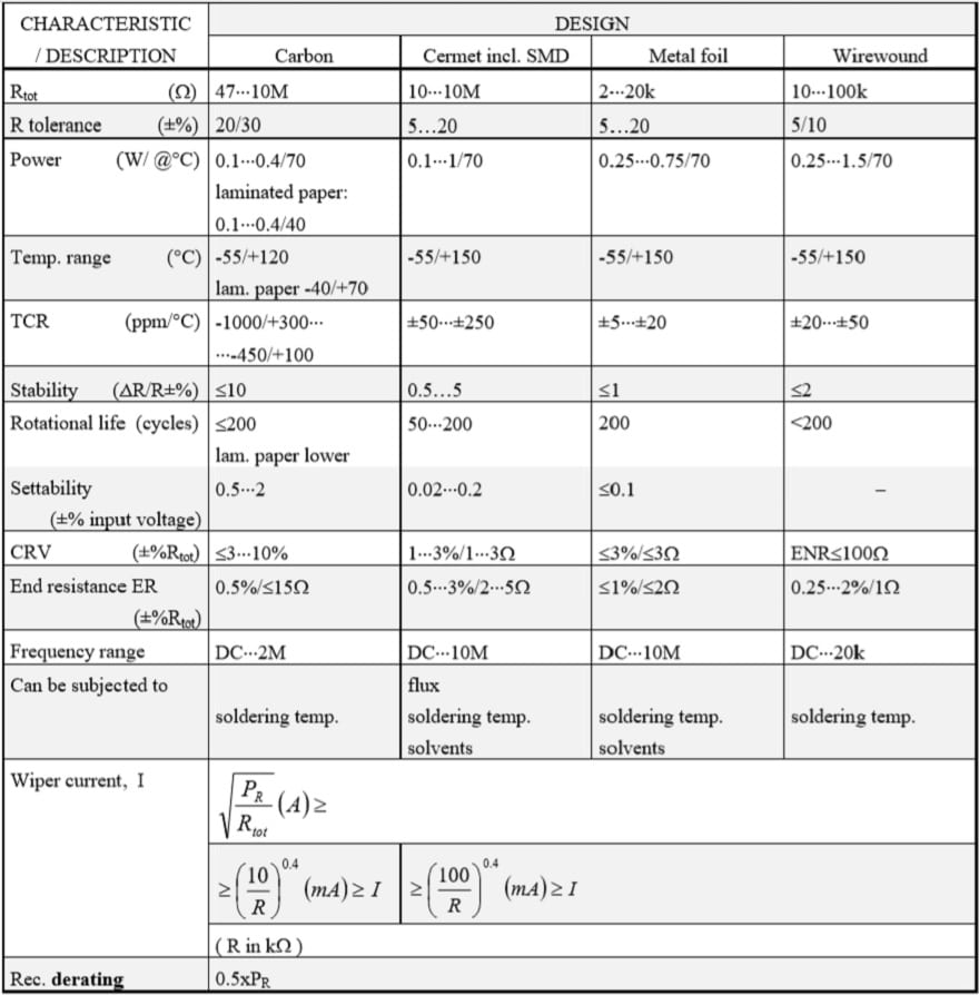
Trimmers
The need for small, adjustable resistors created trim potentiometers. They lack the potentiometer shaft and are operated through an adjustment screw or a rotor. The setting needs to be maintained during handling and environmental influence. Thus, the contact pressure of the wiper is high. The setting stability is specified as a voltage change expressed in percent of input voltage. The first trimming potentiometers had a carbon track or a wirewound element. The carbon track potentiometers exist in a variety of designs, both for surface mount and hole mount, from the cheapest and most simple designs with a substrate of bakelite paper or the like and a sprayed suspension to conductive plastic on a ceramic substrate. The most predominant material, however, is cermet, not least due to the breaking into the market of SMD designs.
Wirewounds still exist due to their better tolerances and lower TCR. But this design suffers sensitivity to a basic mechanical problem. On one hand the wire has to be thin in order to achieve high resistance values, on the other the contact pressure from the wiper needs to be high in order to give a stable setting and a low noise. After a few trim operations the wire might be pulled in two. Moreover the corrosion risk is high if moisture gets inside the housing of the trimmer. With the better and better characteristics that characterize the cermet trimmers of today the need for wirewounds has strongly decreased. If we need better characteristics we preferably should use metal foil trimmers, in spite of their higher price. Just as conventional potentiometers, trim potentiometers are also encapsulated with O ring seals for more severe environments.
SM trimmers that will be subjected to washing fluids should at least have a design that is tight enough to withstand the rinsing process. Otherwise rinsing products like flux residues may deposit on the track which can cause severe contact disturbances. Hole mount types may entice someone into bending the leads. Then it is important that the lead inlets in the potentiometer housing are relieved. Otherwise forces easily are transferred to the joints with the resistance track and its substrate. In consequence either the substrate or the solder joint cracks, thus resulting in an open-circuit.
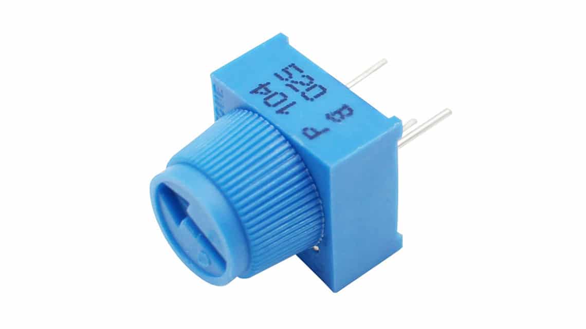
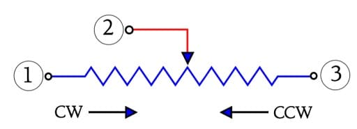
Talking of cracks, the long multi-turn rectangular 1¼” trimmers of the same basic design as the one in Figure R636 are more sensitive to exterior mechanical forces than the shorter ¾” design. Of course, the latter also has to be handled with care. The ¾” size fortunately has more and more replaced the 1¼” style and is itself being replaced by the more common 3/8” or ½” square styles. The square types exist in single-turn designs as well as ¼” and 4 mm diameter potentiometers. SMDs exist as single-turn styles in sizes of 3 or 4 mm square, the latter also in a multi-turn design. Just as hole mount potentiometers the trimmers are marked with movement direction (Figure R4-33).
Trimming potentiometers shall, after trimming, maintain their setting without any alterations. Thus, as said before the contact pressure is high. This means, however, that the rotational life suffers by reduction. The number of cycles – wiper travel backwards and forwards along the track – seldom are specified for more than 200 cycles; for general purpose trimmers even less. Staking in high reliability applications is often used to maintain settings once a circuit is trimmed.
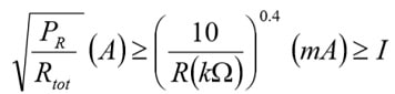
The wiper current must not exceed certain specified maximum values that for wirewound and cermet potentiometers may range as high as to 100 mA. Furthermore, for minimizing the noise the wiper current should be kept above certain minimum values. Both the maximum and minimum values are determined by rated resistance and track material. The following formulas may serve as a guidance at the same time as they contain certain derating information. If the resistance value in question is called R and is expressed in kΩ when we insert it in the “0.4 power fraction” we get the following conditions.
Cermet and wirewound:
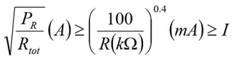
Example. R=100 Ω gives I=[100/0.1]0.4 ≈ 16 mA
Carbon track and conductive plastic:
Example. R=100kΩ gives I=[10/100]0.4 ≈ 0.4mA.
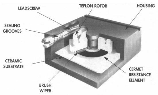
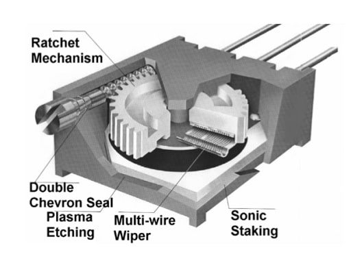
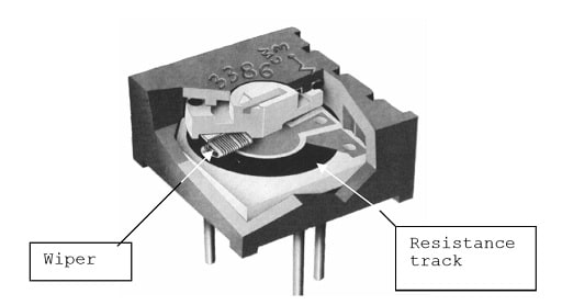
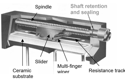
As already mentioned the trimming potentiometer designs and sizes vary significantly. Round, cheap single turn carbon or cermet track trimmers exist, with a varying degree of sealing, both for SM or hole mount applications. Multi- turn trimmers in round, square and rectangular housings exist, with a varying degree of sealing and wear resistance. Because there are no multi-turn tracks a mechanical gear change is used. By means of an adjustment screw and a worm gear and a circular track or a geared spindle drive – a kind of screw where the “nut” serves as holding fixture for the wiper – and a long straight track the multi-turn function is accomplished. Figure R4-34, -35, 36 and –37 show some cutaway views from the manufacturers BI technologies and Bourns.