
Metal Film Resistors
R 3.3 METAL FILM / THIN FILM

Today the most dominant type of resistor is the metal film. Sometimes it is called thin film. From the beginning precious metals or resistive alloys were evaporated in a vacuum process and evaporated on ceramic rods. But the TCR specifications especially were hard to fulfil (TCR = temperature coefficient of resistance). Stability and TCR accuracy took a leap forward when one passed to metal ion bombardment of the rods (so called sputtering). Today all the techniques have been developed and refined.
The evaporation technique works both with a vacuum process and a chemical volatility process. Sputtering and ion implanting have become synonymous concepts. The technical progress today motivates manufacturing of high precision resistors. We talk about the third generation of metal/thin film resistors.
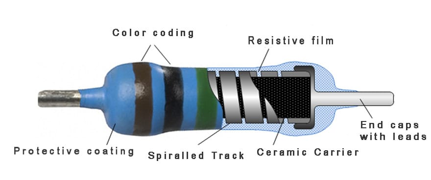
Common film alloys are nichrome (CrNi) or tantalum nitride (TaN), often with additives of aluminum (Al), silicon (Si) or titanium (Ti). The tantalum nitride has very fine low noise characteristics and is superior in hi-fi applications. Generally, metal film resistors keep noise down by means of laser spiraling that properly utilized produces even tracks free from irregularities.
Occurrence of non-linearity – distortion – is mastered by measurement of the third harmonic distortion and automatic screening, where failing parts not meeting stated requirements are removed from the lot.
Distinctive of the metal films is their thin layers – 50…5000 Å or, 0.005…0.5 μm (0.2 …20 microinches). The thinnest films correspond to the highest resistance values where the film starts approaching molecular thicknesses and to some extent deviates from the noise-free conduction capability of metals. Thus the noise is increasingly greater in the high resistance range. Films thinner than 350 Å should be avoided in noise sensitive designs. Another reason for avoiding them is their extreme sensitivity to moisture related electrolytic corrosion, especially if the film consists of a chromium-nickel alloys. Since the film thickness is not stated in the data sheets we may obtain a certain guidance of where the film is getting too thin for high-reliability applications by dividing the manufactured maximum value by 10. Then choose from several serious manufactures the highest manufactured value of the size in question. If the maximum value is, for example, 15 MΩ this rule of thumb gives an upper limit value of 1.5 MΩ. If the application is a dry room environment without large temperature variations (no risk of condensation) and low noise requirements we may use considerably higher resistive values. But still we should, both for reliability and above all availability reasons, take care not to use the highest manufactured maximum value.
Check with other serious manufacturers where their maximum values are and purchase a little bit below the lowest maximum value.
Also, the relatively thickest films are thin and corrosion disposed in moisture, especially if they are working with DC loads. A good encapsulation therefore is necessary. US MIL components exist with hermetic seals but they are relatively expensive. Epoxy/plastic molding does not always offer the same good protection as lacquered coverings, at least not if the lacquer is applied in several thin layers. Farthest in there are one or several – often transparent – coatings of lacquer followed by several layers of colored lacquer. Here the Europeans are far ahead. Duplicated production of cheap standard components with multilayer lacquered coverings probably will come rather close to optimum with regard to price and quality.
Another risk zone for metal film resistors is the ESD – electrostatic discharge. The closer the tolerances, the more important is part protection against ESD.
Finally, metal film resistors are sensitive to power pulses. The power will warm up the thin resistance track very rapidly. Consequently also short pulses may lead to a risk of burning-off or too high temperatures that may hazard the stability. Conservative recommendations talk of maximum 2 x PR where PR stands for rated power. At all events we should not exceed 4 x PR even if the mean power is within specified limits. Single pulses may be much higher but we have to inquire into every particular case: type, manufacturer, value, environment…
R 3.3.1 Low ohmic designs
Values below 10 ohms previously have been manufactured so that the ceramic rods are plated with a resistive alloy, in a bath or a burning process, or by electroplating. The plated layer then will become proportionately thick – between 1 and 5 μm (0.04 and 0.2 mils) – and will have a very good pulse power capability. But tolerances and TC values will be poorer. In the lowest resistance values there is no spiraling which will improve the pulse capability further.
Today some manufacturers have succeeded in producing low ohmic resistors down to 0.1 ohm with the sputtering technique. This eliminates the plating technique difficulties with TCR and tolerance but impairs the pulse capability.
R 3.3.2 Power and precision types
If we load a conventionally power rated metal film resistor with a higher power the temperature will raise and this in turn will decrease stability. Thus power resistors in metal film often have the tolerance ±5% in the E24 series. Alloys and lacquers have been chosen in order to endure higher operation temperatures.
If we go in the other direction and reduce the power – derate – and, moreover, lower the maximum permissible ambient temperature, we get a very stable resistor. IEC 115-5 divides in that way the same sizes in different stability classes, from 0.5 to 0.05 %. It’s the same philosophy as behind Figure R2-9 for precision wirewound resistors. High stability resistors can be worth producing in fine tolerances and TC values. Thus precision resistors of the market are characterized by a low power rating, fine tolerances, low TCR values and a high stability. Note, however, that TC information sometimes is connected to restrictions in the temperature range. The finer the TC, the more narrow the temperature range.
In order to increase the stability further, high precision components are subjected to aging processes where one already under the manufacture releases prospective changes.
R 3.3.3 Linear PTC designs
If we choose metal film alloys that bring out the positive TC of the metals – positive temperature coefficient, PTC – we get relatively linear PTC resistors. Values between +2000 and + 6500 ppm/°C are offered. Just as for the wirewound counterparts the resistance range is limited upwards.
R 3.3.4 Mounting
At least 0.5 mm air space or additional insulation should separate the resistors from adjacent metal parts, for example conductive patterns on printed circuit boards.