
Resistor Standards and Marking
Several standards exist to harmonize resistors throughout the world.
- IEC 60062 Marking codes for resistors and capacitors
- IEC 60115 / JIS C 5201 Fixed resistors for use in electronic equipment
- MIL-STD-202 MIL electronic and electrical component parts
- MIL-R-87254 – Resistors, fixed, film, high reliability
- DIN 44 052 – Resistors, fixed, lacquered, cracked carbon film, high stability, with axial leads – CANCELLED replaced by IEC 60115
- EN 140 000 – Generic Specification: Fixed resistors – CANCELLED replaced by IEC 60115
To identify the value of axial resistors, a resistor color code is used. This color code consists of several colored bands. Surface mount resistors are identified by a numerical resistor code. The nominal values of resistors are also standardized. Several ranges of preferred resistor values are available. Another important aspect of resistor standardization is the use of standardized resistor symbols. The IEC standard symbol of a fixed value resistor is shown.
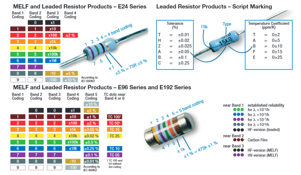
Resistor values are often indicated with color codes. Practically all leaded resistors with a power rating up to one watt are marked with color bands. The coding is defined in the international standard IEC 60062. This standard describes the marking codes for resistors and capacitors. It includes also numerical codes, as for example often used for SMD resistors. The color code is given by several bands. Together they specify the resistance value, the tolerance and sometimes the reliability or failure rate. The number of bands varies from three till six. As a minimum, two bands indicate the resistance value and one band serves as multiplier. The resistance values are standardized, these values are called preferred value.
Resistor color code chart
The chart below shows how to determine the resistance and tolerance for resistors. The table can also be used to specify the color of the bands when the values are known.
Tips for reading resistor codes
In the sections below examples are given for different numbers of bands, but first some tips are given to read the color code:
- The reading direction might not always be clear. Sometimes the increased space between band 3 and 4 give away the reading direction. Also, the first band is usually the closest to a lead. A gold or silver band (the tolerance) is always the last band.
- It is a good practice to check the manufacturer’s documentation to be sure about the used coding system. Even better is to measure the resistance with a multi-meter. In some cases this might even be the only way to figure out the resistance; for example when the color bands are burnt off.
Color code exceptions
Reliability band
Resistors that are produced according to military specifications, sometimes include an extra band to indicate reliability. This is specified in failure rate (%) per 1000 hours of service. This is rarely used in commercial electronics. Mostly the reliability band can be found on four band resistors. More information about the reliability can be found in the US military handbook MIL-HDBK-199.
Single black band or zero-ohm resistor
A resistor with a single black band is called a zero-ohm resistor. Principally it is a wire link with only function of connecting traces on a PCB. Using the resistor package has the advantage of being able to use the same automated machines to place components on a circuit board.
5 band resistor with a 4th band of gold or silver
Five band resistors with a fourth band of gold or silver form an exception, and are used on specialized and older resistors. The first two bands represent the significant digits, the 3th the multiply factor, the 4th the tolerance and the 5th the temperature coefficient (ppm/K).
Deviating colors
For high voltage resistors often the colors gold and silver are replaced with yellow and gray. This is to prevent having metal particles in the coating.
Chip Resistors Marking
Resistors have the resistance marking in three or four alpha-numerals on the top surface. Some small size resistors have no marking.
3 digits
The 1st and 2nd digits are significant of resistance shown in E3, E6, E12 and E24. The 3rd digit means the multiplier numbers of zero to follow. R means a decimal point. L means a decimal point of resistance expressed by mΩ.
4 digits
The 1st, 2nd and 3rd digits are significant of resistance shown in E96 and E196. The 4th digit means the multiplier number of zero to follow. R means a decimal point. L means a decimal point of resistance expressed by mΩ.
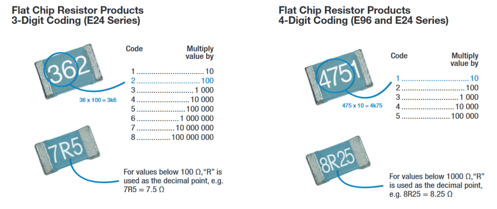
Examples:
3 digits:
- 153: 15×103 = 15kOhm
- 1R5: 1.5Ohm
- 1L5: 1.5mOhm
4 digits:
- 1542: 154×102 = 15.4kOhm
- R154: 0.154Ohm
- 15L0: 15.0mOhm
Standard resistor values
Resistance and tolerance values are defined into a norm, to ease the mass manufacturing of resistors. These are referred to as preferred values or E-series, and they are published in standard IEC 60063:1963. These standard values are also valid for other components like capacitors, inductors and Zener diodes.
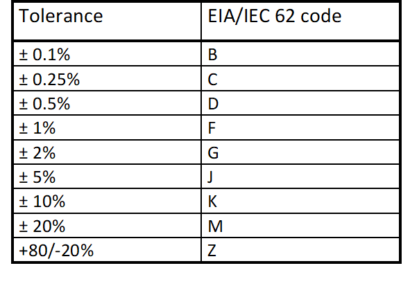
Following international standards 60063 and EIA/IEC 62, capacitance values and tolerances are standardized as follows:
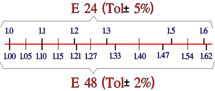
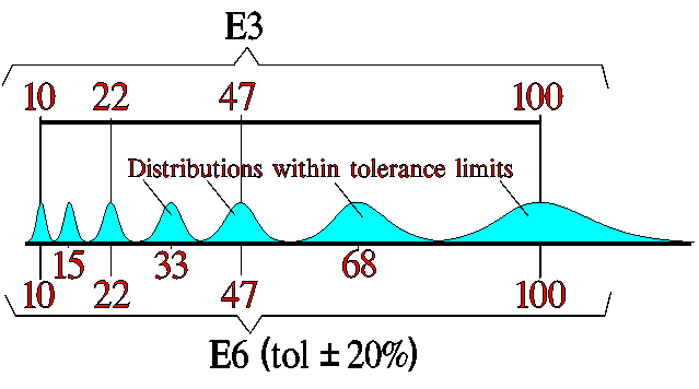
E range
Capacitance is following standardized “E ranges” defined per logarithmic-steps such as E3, E6 … E24, E48 steps.
Naturally, the selected E-range is also linked to the tolerance field – not to overlap between the next capacitance tolerance range – see bellow.
Specific capacitor technologies’ E range is driven by its capability to produce reproducible and tight tolerance capacitance value in mass production. You can find the relevant capacitance values and tolerance ranges defined in manufacturers’ catalogues.
![]() Resistor Color Marking Explained
Resistor Color Marking Explained
ilecture online 4:17min