Metal Foil Resistors
R 3.4 METAL FOIL
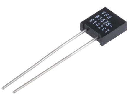
Within the metal film technology there is a particular type of precision resistor made by metal foils, by the inventor, Vishay Intertechnology, called Bulk metal foil. These resistors exist both in axial and radial designs for hole mount, further as SMDs, networks and power styles, finally also in PTC designs.


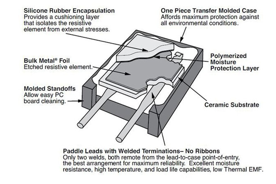
Figure R3-5 shows a principle cutaway view of a foil resistor from the manufacturer Vishay. The etching pattern is not shown.
The coefficients of the thermal expansion of the resistance alloy and substrate are different. When the alloy foil is firmly attached to the ceramic substrate in a unique way it results in a compressive stress on the alloy when temperature increases. The resistivity of the alloy versus temperature changes is matched with variations of the resistance of the alloy with stress. In other words, by this method the physical expansion behavior of the foil is forced to follow the considerably lower expansion or shrinkage movements of the substrate at temperature changes. This results in a foil with excellent stability and TCR characteristics. The construction also results in outstanding characteristics of thermal electromotive forces and voltage coefficients.
The foil then is etched to a serpentine or labyrinth pattern, either by means of a photo resistive film, mask and chemical etching (photo lithography), or by means of a guided ion beam. Particular, not mold encapsulated styles, can be bought together with trimming tools. By scribing an open-circuit in particular conductance paths the resistance value may be trimmed to extremely fine tolerances. The patterns eliminate much of the inductance that burdens spiraled components.
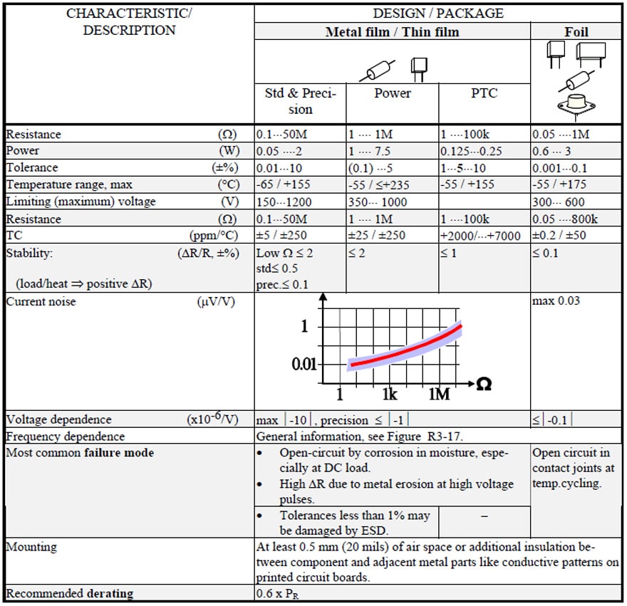
Since the foils have thicknesses of more than 2.5 μm (0.1 mil) they have excellent pulse resistant characteristics. They don’t suffer from the extreme corrosion sensitivity of thin films either. The disadvantage is that the maximum resistance of metal foil styles will be limited (See Table R3-1).
The most common failure mode of metal foil resistors is open-circuit in contact joints after temperature changes or of shifts in resistance as debris or weak spots in the resistive path burn out.
Table R3-1. METAL FILM & METAL FOIL RESISTORS[1]

Ten Technical Reasons to Choose VFR Resistors for Your Circuit; pdf; VPG Foil Resistors' Technical Document
