
Construction Types and Manufacturing Process of Aluminum Capacitors
There are more types of aluminum electrolytic capacitors construction and termination styles:
- SMDs (V-chip) for surface mounting on printed circuit boards or substrates
- Radial lead terminals (single ended) for vertical mounting on printed circuit boards
- Axial lead terminals for horizontal through hole mounting on printed circuit boards
- Radial pin terminals (snap-in) for power applications
- Press-fit terminals
- Large screw terminals for power applications
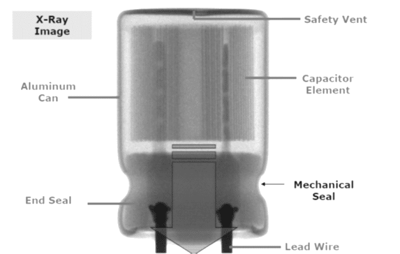
The most common styles are wound foil capacitors packaged in aluminum can as leaded or SMD termination styles.
Electrolyte can be wet, gel (TCNQ salt), solid (conductive polymer) or hybrid (combining wet and conductive polymer) based:
Wet Liquid Types
- 4 ~ > 500V
- high ESR
- poor temp performance
- dry out, cap decrease with life
- low cost
Solid Conductive Polymer
- 2.5 ~ 100V
- low ESR, high ripple current
- stable high and low temperatures
- leakage current stability issues
- higher sensitivity to humidity
- higher cost
Hybrid Wet + Polymer
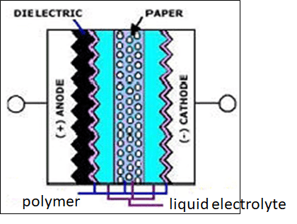
- Up to 125V
- similar ESR as polymer capacitor
- more stable then liquid type
- better leakage current stability vs polymer cap
- higher cost comparing to wet
Manufacturing Process:
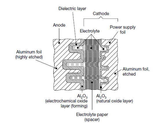
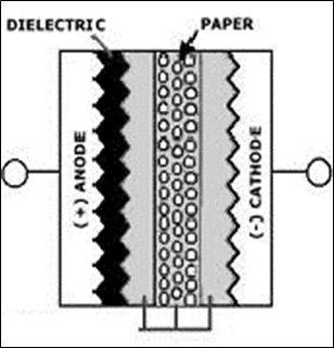
The production process starts with mother rolls. First, the etched, roughened and pre-formed anode foil on the mother roll as well as the spacer paper and the cathode foil are cut to the required width.
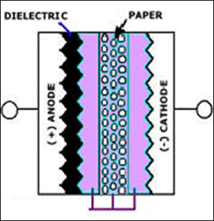
The foils are fed to an automatic winder, which makes a wound section in a consecutive operation involving three sequential steps: terminal welding, winding, and length cutting. In the next production step the wound section fixed at the lead out terminals is soaked with electrolyte under vacuum impregnation.
The impregnated winding is then built into an aluminum case, provided with a rubber sealing disc, and mechanically tightly sealed by curling. Thereafter, the capacitor is provided with an insulating shrink sleeve film. This optically ready capacitor is then contacted at rated voltage in a high temperature post-forming device for healing all the dielectric defects resulting from the cutting and winding procedure.
After post-forming, a 100% final measurement of capacitance, leakage current, and impedance takes place. Taping closes the manufacturing process; the capacitors are ready for delivery.
