
POLYSTYRENE (PS), POLYPHENYLENE SULFIDE (PPS) AND OTHER PLASTIC FILMS
C 2.6 POLYSTYRENE (PS) and POLYPHENYLENE SULFIDE (PPS)
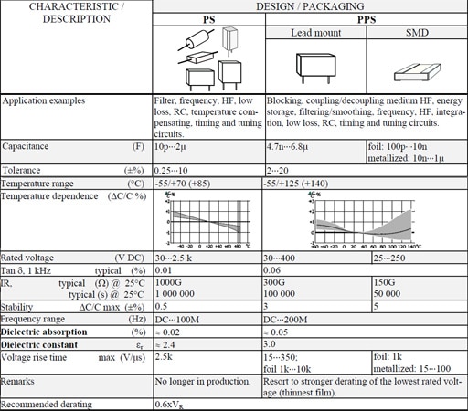
Polystyrene (PS) represents a non-polar dielectric material that just as polycarbonate to a great extent has been replaced by polypropylene. The availability is strongly limited due to ceased production.
Polyphenylene Sulfide or simply PPS has come to stay mainly because of its relatively high temperature resistance which has allowed SMD manufacture.
C 2.6.1 General comments to PS
εr ≈ 2.4. Max. temp.+70°C (possibly +85°C). Smallest film thickness 4 μm (0.16 mils). Except for metal foils often double metallized plastic foils are used.
Advantages
- Very low losses; 0.01% at room ambient and 1 kHz.
- Very high IR; RC 200 000 s. Actually it’s more exterior factors that determines the IR than the material itself.
- Dielectric absorption 0.02%.
- Stability ΔC/C, max ± 0.5%.
Disadvantages
- Can not be metallized due to high carbon deposits and too little oxygen available at a self-healing breakdown.
- Chemically sensitive film.
- Availability limited due to ceased production.
C 2.6.2 Temperature and frequency dependencies for PS
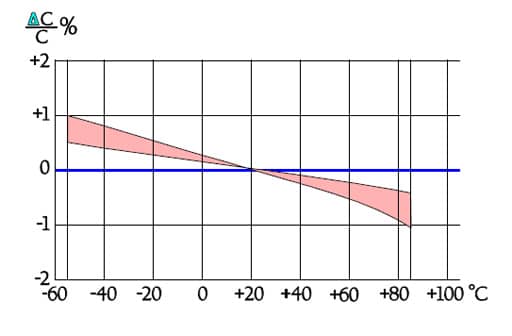
Figure C2-57. Capacitance versus temperature for PS capacitors.
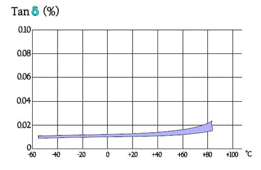
Figure C2-58. Tan versus temperature for PS.
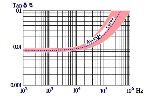
Figure C2-59. Typical curve range for Tanδ versus frequency for PS.
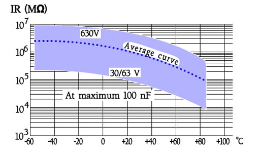
Figure C2-60. Typical curve range for IR versus temperature in PS capacitors, when C ≤0.1μF.
C 2.6.3 General comments to PPS
Foil types exist but metallized design is a rule. If nothing else is said metallized film applies.
εr ≈3.0. Max. temp.+140 °C; most manufacturers recommend maximum +125 °C. Dielectric absorption ≈ 0.1%.
Smallest film thickness is 1.2 μm (0.05 mils) but former quality problems with the thinnest film may give cause for stronger derating of the lowest rated voltage. However, the supply of film is stabilized thus indicating an established demand..
The film is used in capacitors both for lead mount and SMD. Existing chip types are made in a stacked design.
C 2.6.4 Temperature and frequency dependencies for PPS
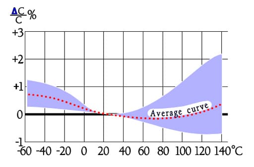
Figure C2-61. Typical curve range for capacitance versus temperature in PPS capacitors.
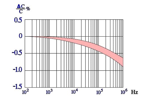
Figure C2-62. Typical curve range for capacitance versus frequency in PPS capacitors.
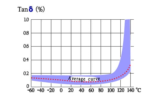
Figure C2-63. Typical curve range for Tanδ versus temperature in PPS capacitors.
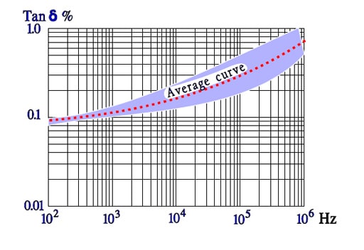
Figure C2-64. Typical curve range for Tan versus frequency in PPS capacitors.
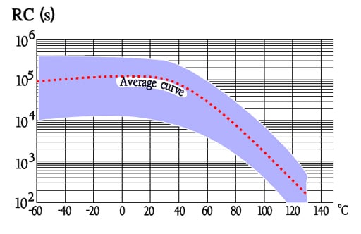
Figure C2-65. Typical curve range for IR versus temperature in PPS capacitors.
Table C2-7. POLYSTYRENE (PS) and POLYPHENYLENE SULFIDE (PPS)
C 2.7 OTHER PLASTIC FILMS
Following selection contains plastic films for special purposes.
C 4.7.1 Teflon (PTFE)
Teflon exists both in metallized and foil design. The greatest advantage of the film is its temperature resistance. The price, on the other hand, is high which gives cause for exclusive hermetic designs.
- Capacitance 470pF….4.3μF.
- Tolerance ±0.25….±20%.
- Temperature range -65/+200°C.
- TC -200…+50ppm/°C.
- Rated voltage 50…600 V DC.
- Tanδ , @ 1kHz, 20°C, ≤0.1%.
- IR, @ 20°C, foil ≥500GΩ/ ≥100 000s,
- IR, @ 20°C, metallized film 50GΩ/ 10 000s.
- Stability ΔC/C max -1%.
- εr ≈ 2.2.
- Dielectric absorption ≤0.02%.
- Recommended derating 0.6xVR.
C 4.7.2 Polysulfone (PSU)
Polysulfone capacitors belong to the same price group as the one of teflon. They are used only in special applications where high temperature capabilities together with excellent characteristics are of vital importance. The capacitors have been manufactured only in hermetic design and with foil electrodes.
- Capacitance 1nF….22μF.
- Tolerance ±0.25….±10%.
- Temperature range -65/+150°C.
- TC -200…+50ppm/°C.
- Rated voltage 50…400 V DC.
- Tanδ , @ 1kHz, 20°C, ≤0.15%.
- IR, @ 20°C, foil ≥1000GΩ
- εr ≈ 3.2.
- Dielectric absorption ≤0.2%.
- Recommended derating 0.6xVR.