MP Paper and MKT / MKP Plastic Film Capacitors
Lets start electrostatic capacitors with paper capacitors – the “pure” paper capacitors are not anymore in often use, but it is good to get familiar with the technology and explain some principles. Metallized paper MP and plastic film MK (MKP and MKT) technologies are still used today as RFI noise suppression capacitors.
C 2.2 PAPER CAPACITORS
Under this headline we deal mainly with pure paper dielectrics. At the same time we ought to say that combinations of paper and plastic, i.e. mixed dielectrics, are rather common.
C 2.2.1 Paper / foil
The history of the commercial capacitor started with paper foil dielectrics and electrodes of aluminum foils. Because paper is porous it has to be impregnated in order to prevent corona effects and flash-overs. It is done by use of melted wax or different kinds of oils, among other things mineral and silicone oils. The oils increase the tensional stability but decrease to a certain extent the εr. Fibrous paper has an εr ≈ 6.6 and the mineral oil ≈ 2.3 which gives the impregnated winding an εr varying between 3.1 and 4.5. The differences depend above all on the winding pressure produced by the tensile force during winding.
Formerly at least two impregnated paper foils were used because of the character of the paper. Today mixed dielectrics are used frequently where the paper is combined with plastic foils, usually polyester (PET) or polypropylene.
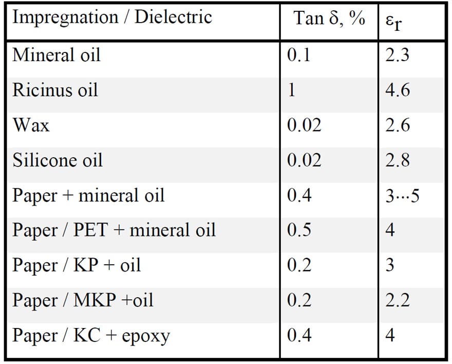
Because the summary tables following each presented material type don’t deal with the impregnation agents and mixed dielectrics separately we mention some of their characteristics in following Table C2-2.
Table C2-2. Tan δ, 1 kHz, and εr for some mixed dielectrics.
Oil impregnated paper is, above all, used in power, mains and in certain feed-through capacitors. In this handbook we restrict ourselves to those smaller types which belong to the electronic components. They constitute an fading component category that more and more is replaced with plastic dielectrics.
In common mains and feed-through capacitors intended for consumer purposes the casings contain only a faint amount of oil. Most of it exist in the paper foils. The impregnation is carried out in vacuum on the finished winding after that the paper first has been dried carefully in an oven.
C 2.2.2 MP (metallized paper)
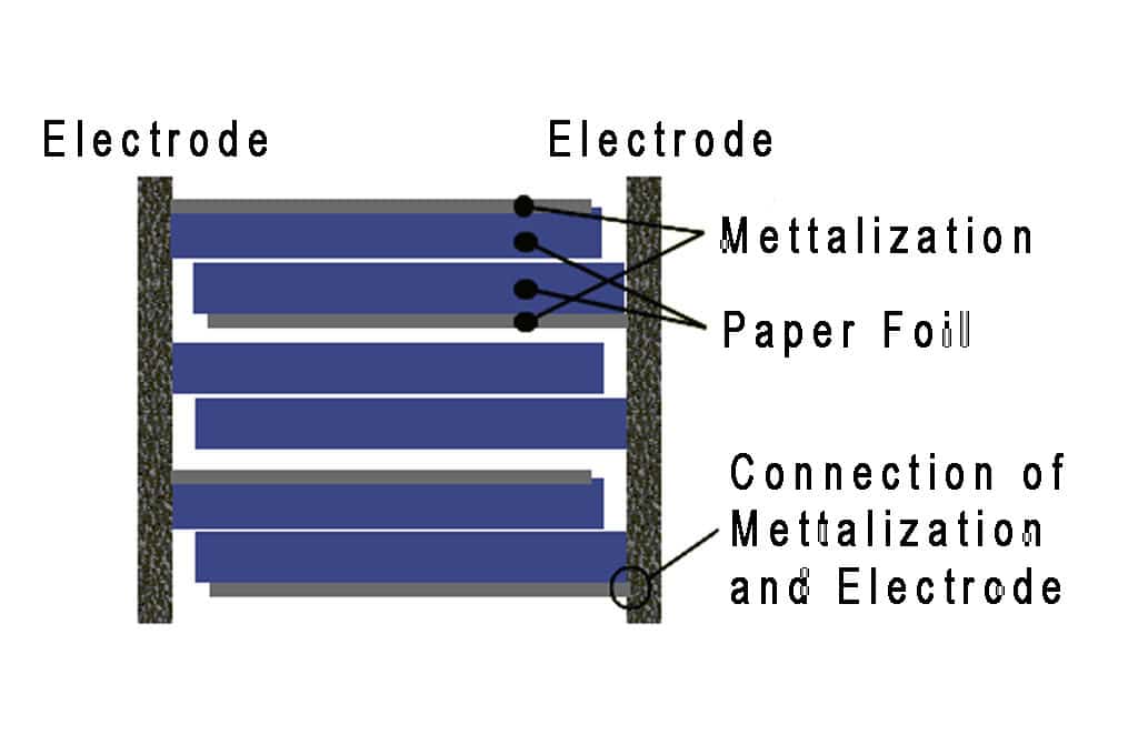
The first metallized film capacitor was built with metallized paper. The MP foil looks in principle like the one in Figure C2-18.
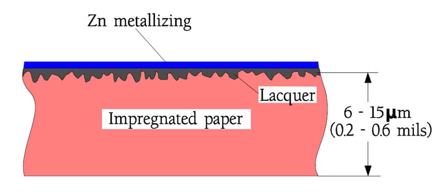
Figure C2-18. Cross-section through an MP foil.
As impregnation agents solid substances like epoxy is predominant but vegetable oils may occur in certain types. The impregnation also protects the zinc metallization against aqueous corrosion and oxidation. Because the paper is porous and in certain points may contain some impurities or weaknesses one must in professional applications use designs with at least two layers of paper foils. The risk that a weak spot in one foil shall land opposite another one in the next layer is minimized. In stead of an extra paper foil nowadays mixed dielectrics are more and more frequently used with a polyester or polypropylene film together with the metallized paper foil. Also occurring are variants with a metallized plastic film and an impregnated paper foil.
The genuine MP capacitor once was falling out of use but concurrently with experiences from the plastic films it has witnessed a well-motivated renaissance. Above all it has to do with the need for transient protecting capacitors in mains applications. According to Table C2-1 the carbon deposit from self-healings produced during manufacture – so called clearings – are uniquely low for cellulose materials at the same time as the necessary energy release stops at completely harmless levels (ΔV ≈ -10 mV… -1 V). See Figure C2-24.
Besides the MP capacitor has another advantage at pulse applications. Pulses mean steep voltage rise times and high charge and discharge currents. The usual zinc metallization together with an end spray metal consisting of a zinc compound (shooping metal) gives just that low ESR in the contact interface that is necessary for avoiding a local heating. Repetitive courses of pulse events may on the other hand create internal heating because of the dielectric losses. If the capacitor is used as an energy storing pulse transmitter part of the energy will be lost in the dielectric loss resistance Rd. The voltage Vc of the charged capacitor will at the discharge be voltage divided in Vd and VL (Figure C2-19).
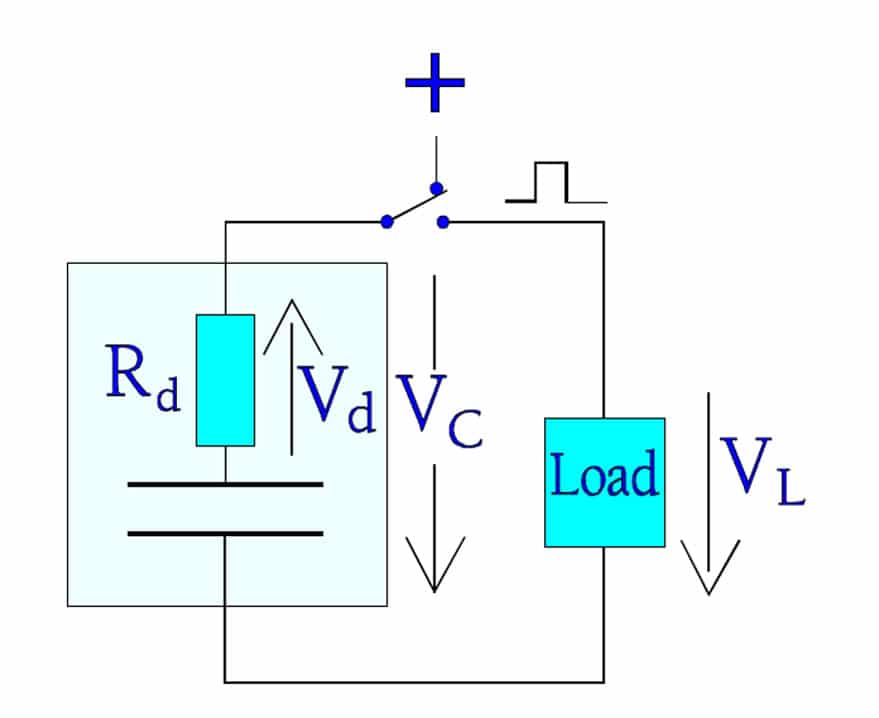
Figure C2-19. Energy loss in the dielectric at a pulse load.
C 2.2.3 Transient suppression / X- and Y-capacitors
In the group of RFI capacitors that shall protect against Radio Frequency Interference so called X- and Y-capacitors are included. They are connected to the mains according to Figure C2-20. There they also serve another important purpose. Transients strike namely every live mains relatively often. They may come from the ”outside” but may also be generated by our own equipment.
Between 80 and 90 % of all transients from the mains last between 1 and 10 μs, are higher than 1000 V, have voltage rise times of 200 to 2000 V/μs and are occurring at least 10 times a day. We realize that their damage must be eliminated. It is done by the X-capacitors which thus are connected between the lines of the mains.
The Y-capacitors represent another type of transient suppression. They are connected between either of the power lines and the grounded cover of electric equipment. Here we require an extra high safety against short-circuits in order to prevent the equipment being put under tension and thus causing serious personal injuries. Besides, the Y-capacitor shall have a limited capacitance in order not to bring about harmfully high currents through the human body in case of a possible open circuit in the ground wire (see Figure C2-20).
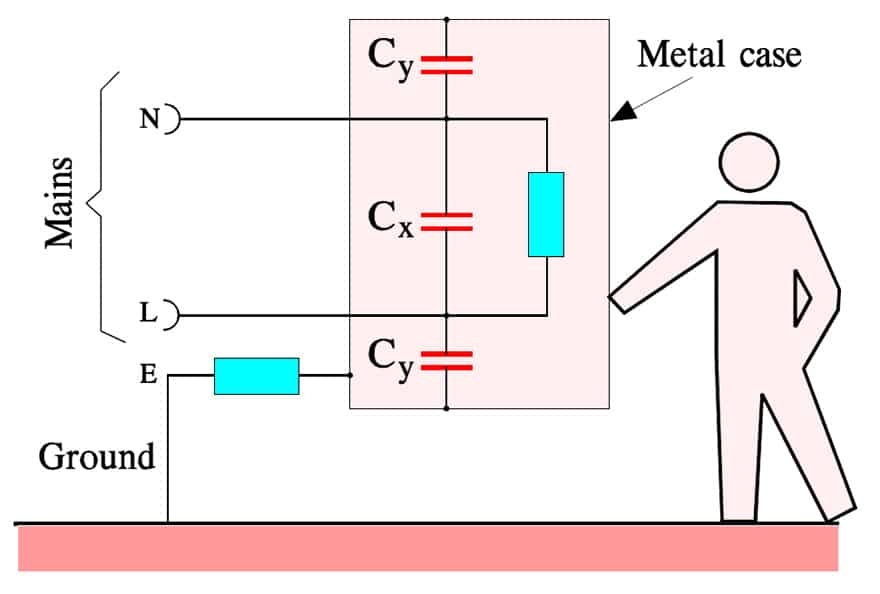
Figure C2-20. Connecting of X- and Y-capacitors.
In order to verify that the X- and Y-capacitors really can withstand occurring transients they must pass the following three tests without remarks.
- Life test according to IEC 384-14, 1000 hrs at Tuc and 1.25xVR + 1000 Vrms every hour for 0.1 s.
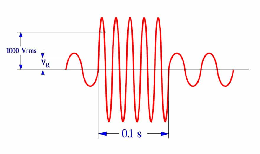
Figure C2-21. Life test of X- and Y-capacitors.
- Surge voltage test according to 384-14. Three pulses of Vp = 2.5 to 5 kV depending on capacitor type.
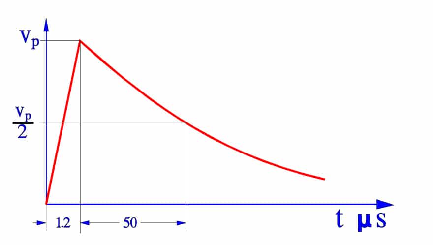
Figure C2-22. Surge voltage test of X- and Y-capacitors.
- Charge and discharge test according to IEC 384-14. 10 000 pulses at 100 V/s and 2xVR.
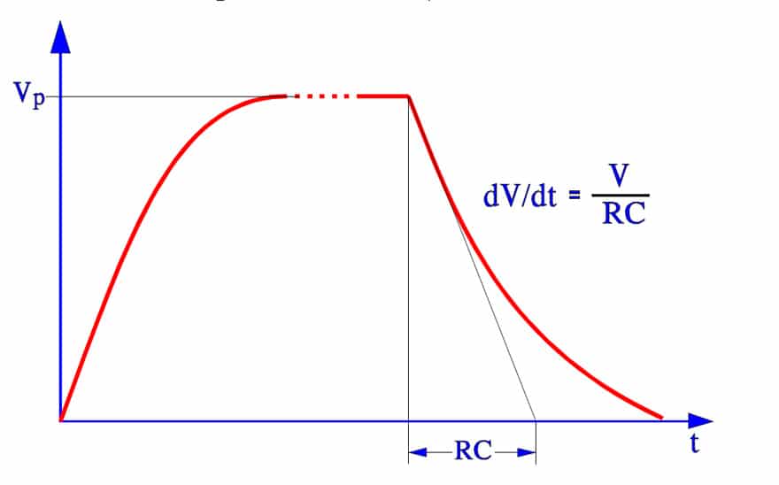
Figure C2-23. Charge and discharge test of X and Y capacitors.
X- and Y-capacitors must have an approval by national inspection authorities in order to be used in respective countries. In the manufaturers’ catalogues it could be written ”approved by SEMKO” (Sweden), by DEMKO (Denmark), by VDE (Germany), by UL (USA), by BSI (Great Britain) etc. Now all European check routines are collected in one standard, EN 13 24 00. The USA standards are collected under UL and the Canadian under CSA.
MP or MK?
In X- and Y-capacitor applications we have to count on self-healing breakdowns. The voltage drop caused by a self-healing depends on the energy that is consumed in order to evaporate dielectric and metallizing. Here MPs with their zinc metallizing have been superior to plastic film capacitors which by tradition have had an Al metallization whose evaporation process requires several times higher energy than Zn. Nowadays, however, plastic film capacitors (MK) are brought on the market with metallization alloys based on the advantageous characteristics of zinc but without its tendency towards aqueous corrosion.
Further on there exist special designs of metallized plastic films where a segmented metallization is used, sometimes called a structure metallization. The surface is divided in mutually demarcated elements that are within reach of the charging current via narrow gates. At a self-healing the surge current burns them off. See example in Figure C2-25 and -26 below. The surface element is isolated and the discharge current from other elements is cut off as well as the beginning voltage drop. One gets approximately the same energy limitation as by a self-healing in an MP capacitor, especially if the structure metallization is combined with choices of modern metallizing alloys. Following Figure C2-24 shows typical self-healing effects on the voltage drop over a capacitor.
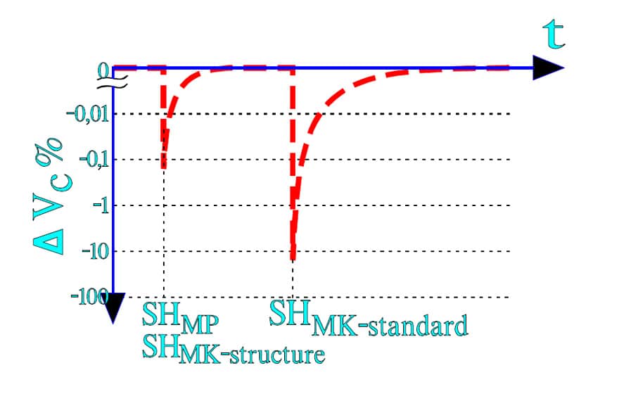
Figure C 2-24. Typical voltage drops DVC at a self-healing (SH) in an MP and an MK capacitor under tension. SHMP » SHMK-structure.
The metallized plastic films (MK) that hitherto have been used are polyester (MKT) and polypropylene (MKP). The latter need not be structure metallized due to its excellent self-healing chemistry. Combined with very thin ZnAl metallizing the design gets the same characteristics as structure metallized MK. In addition its high frequency characteristics are superior to those of other films.
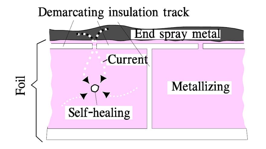
Figure C 2-25. Example of a structure metallized foil and the self-healing current.
The metallizing in structured surface elements makes great demands for the design. Even if cost-effective methods are developed they involve a certain rise in prices. The simplified segmented metallization in Figure C2-25 actually consists of a grid-like pattern that is distributed over the whole surface.
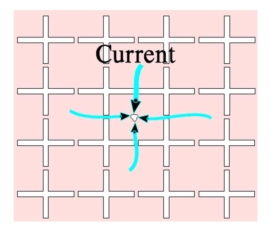
Figure C2-26. Grid-like metallization pattern.
Another, and very interesting, structure metallization consists of metallized circular surfaces on top of a thin, high surface resistivity metallizing that covers the total surface. The weak circular joints serve together with the thin underlying metallization as fusing elements. The fusing function is favored by a metallization of zinc or low energy alloy.
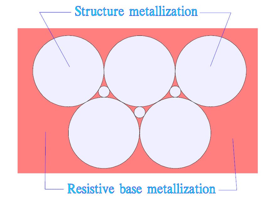
Figure C2-27. Schematic of segmented metallization.
Every self-healing reduces the capacitance correspondingly to the surface reduction. The author’s opinion is that the MP capacitor still is superior to structure metallized MK types. But, of course, both types meet current standards and safety requirements.
C 2.2.4 Temperature and frequency dependencies
Following diagrams show some typical graphs for the temperature and frequency dependence of paper capacitors.
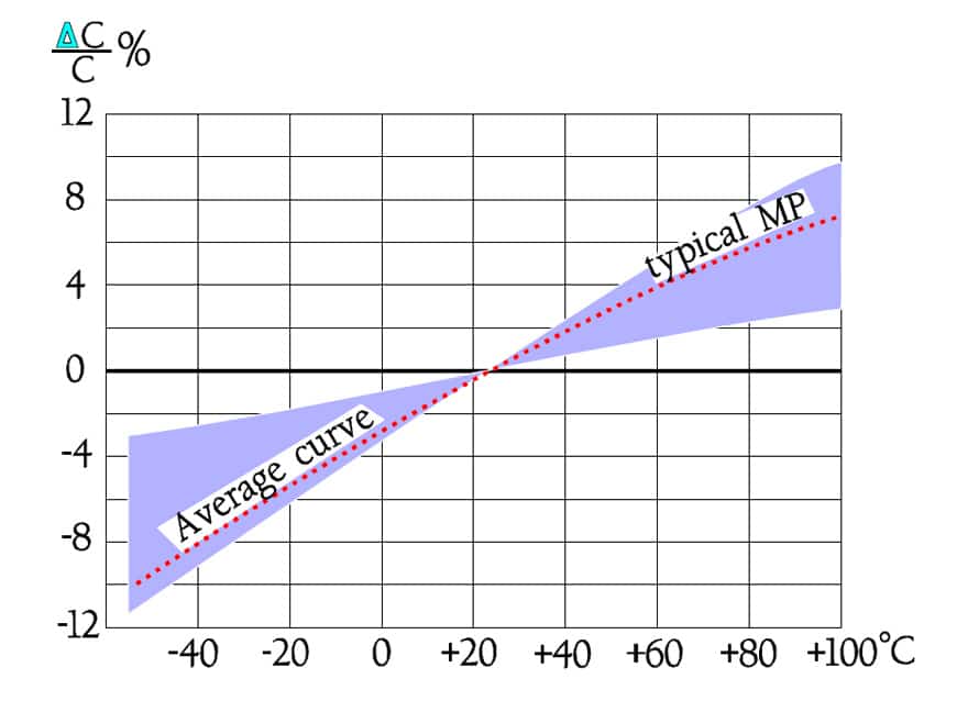
Figure C2-28. Capacitance C versus temperature T for MP and oil impregnated paper capacitors.
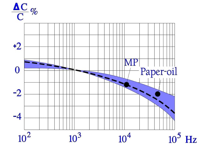
Figure C2-29. Typical frequency dependence of the capacitance for paper capacitors.
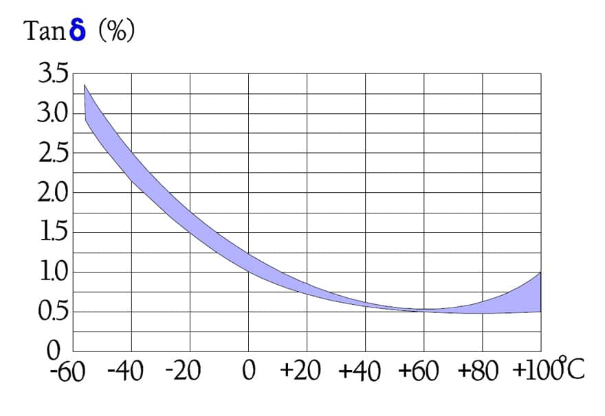
Figure C2-30. Typical temperature dependence of the dissipation factor for an MP capacitor.
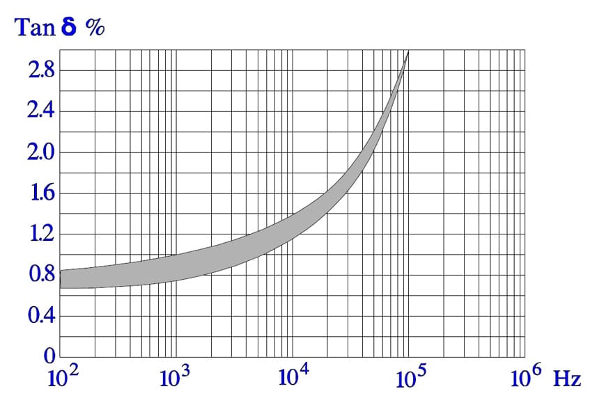
Figure C2-31. Typical frequency dependence of the dissipation factor for an MP capacitor.
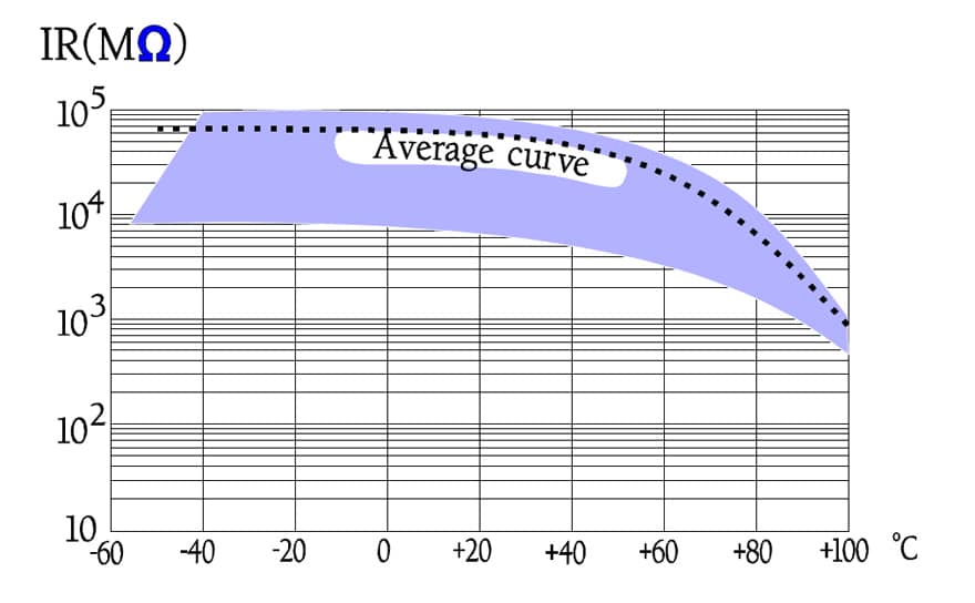
Figure C2-32. Typical curve area for the temperature dependence of the IR for MP capacitors.
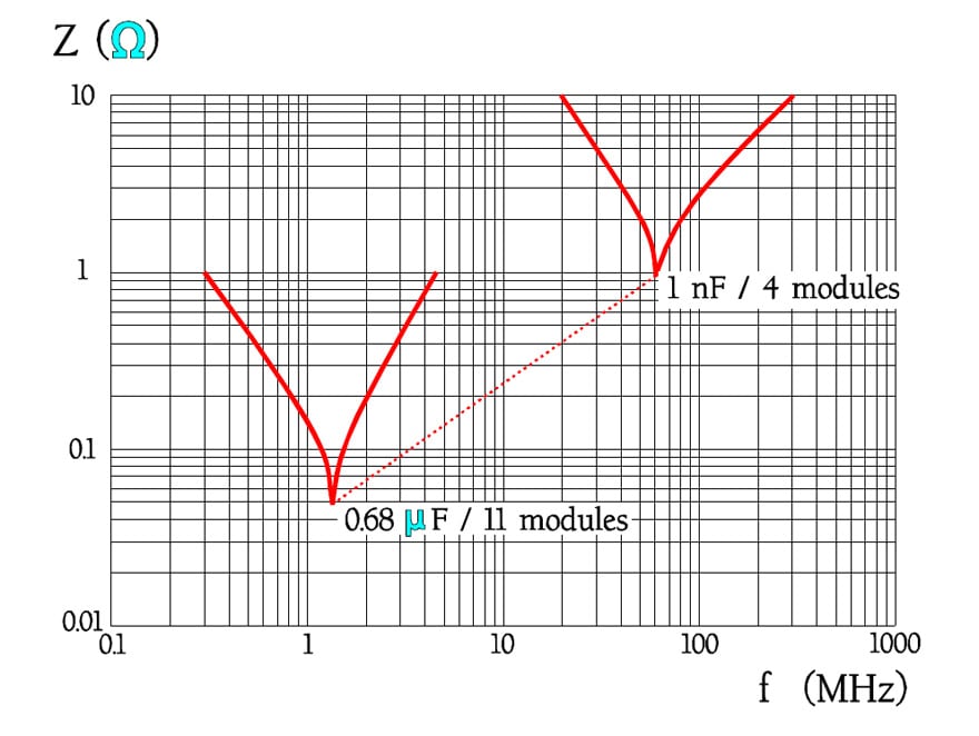
Figure C2-33. Examples of impedance versus frequency for MP capacitors with different capacitance and lead space.
In Figure C1-17 we can see how the impedance curve touches the bottom of ESR losses like a pliable curve long before the capacitive branch cuts the inductive one. In Figure C2-33, however, the impedance curve turns down in a sharp point around the resonance frequency. The differences have to do with the losses. In low-loss components like film capacitors the decreasing capacitive reactance curve reach areas around the resonance frequency before it get to the limiting ESR contribution. Here the reactance drops even faster than according to the initial curve because of the counteracting inductive reactance.
The tip of the impedance curve in Figure C2-33 is in a larger magnification not so sharp that is indicated in the diagram. See example in Figure C2-43.
(In capacitors with rather high losses as, for example, electrolytics the reactance curves reach the ESR contribution at frequencies far away from the resonance frequency. Here produces the dipole dependent capacitance decrease a deviation upwards from the initial reactance curve, as shown in Figures C1-17 and 20).
C 2.2.5 Failure modes
Penetrating moisture represents the greatest threat against paper capacitors because the paper absorbs humidity that in turn affects the IR and damages the dielectric. Concerning hermetic components, see C 2.1.9. In foil capacitors internal, freely suspended terminal wires run the risk of vibrating to disruption.
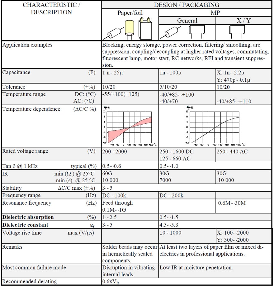
Survey table
Just as concerning resistors we conclude every material group with a survey table. Two electrode designs occur: metallized and foil. When we in the headings write foil or met it thus refers to the electrode type.