
Film Capacitor Construction and Manufacturing
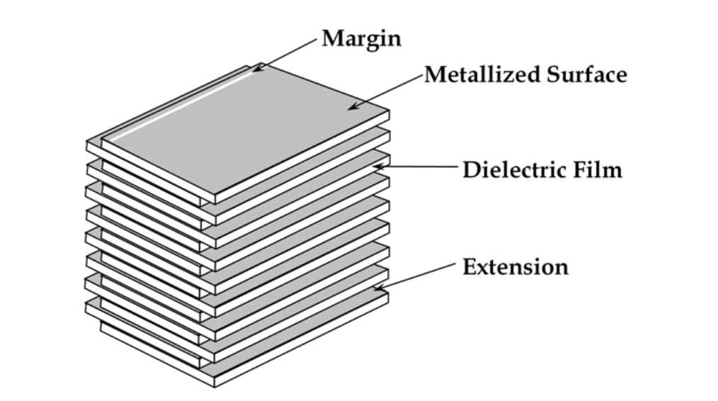
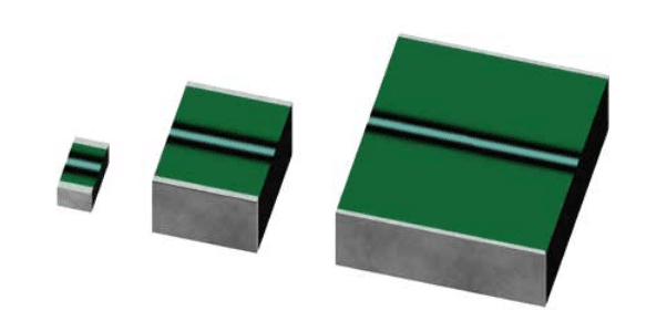
Film capacitors can be produced as wound or stacked foil capacitors types depending to the final application requirements and features – see figures bellow. Minimum rated voltage of film capacitors is mostly limited by its mechanical strength to withstand the winding process and it starts typically from >3um per layer corresponding to ~30V, thus it is not direct competition to low voltage SMD other capacitor technologies.
The exception is multilayer SMD stacked capacitor Rubycon PMLCAP(R) that employs electron beam curing resin as the dielectric material and vacuum deposition polymerization technology as manufacturing method that enable dielectric thickness to be less than 1um allowing minimum voltage (and high capacitance) from 10/16V and offer alternative to MLCC class I capacitors even at low voltage applications.
Construction
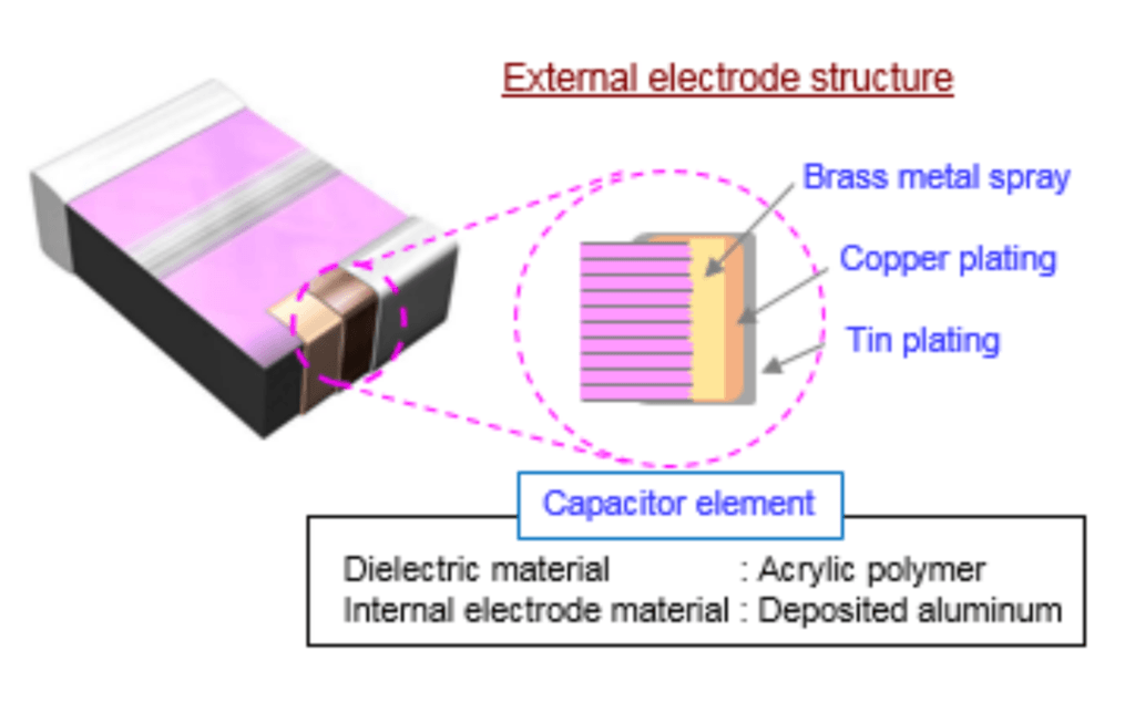
multilayer SMD film PMLCAP: source: Rubycon
Polar Plastics Vs Non-polar Plastic Dielectrics
Dielectric properties of a polymer largely depend upon their structure. The structure determines whether a polymer is polar or non-polar and this in turn decided the electrical properties of the polymer.
- In polar polymers (PMMA, PVC, Nylon, PC etc.), dipoles are created due to imbalance in the distribution of electrons. These dipoles tend to align in the presence of electric field. Hence, this creates dipole polarization of the material making these materials only moderately good as insulators.
- While non-polar polymers (PTFE, PP, PE, PS) have symmetrical molecules and are truly covalent. There are no polar dipoles present in them and hence in presence of electric field does not align the dipoles. However, slight electron polarization occurs due to the movement of electrons in the direction of electric field, which is effectively instantaneous. These polymers have high resistivities and low dielectric constant.
Polar plastics have a tendency to absorb moisture from the atmosphere. Presence of moisture raises the dielectric constant and lowers the resistivity. With rise in temperature, there is faster movement of polymer chains and fast alignment of dipoles. This invariably raises the dielectric constant values for polar plastics.
Non-polar plastics are not affected by moisture and rise in temperature. Dielectric constant of various plastic materials can be found in the post linked in material folder of this lesson.
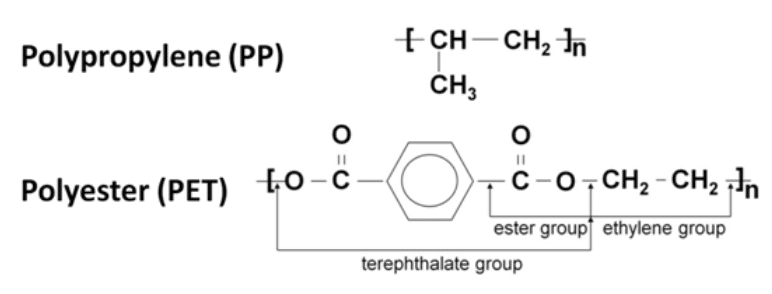
PET and PP totally dominate the film capacitor dielectric market. PP is a small and simple molecule. PET is „heavier” but also provides a stronger and higher tensile strength film that con be bi-axially oriented into very thin films.
Manufacturing Process
The following example describes a typical manufacturing process flow for wound metallized plastic film capacitors.
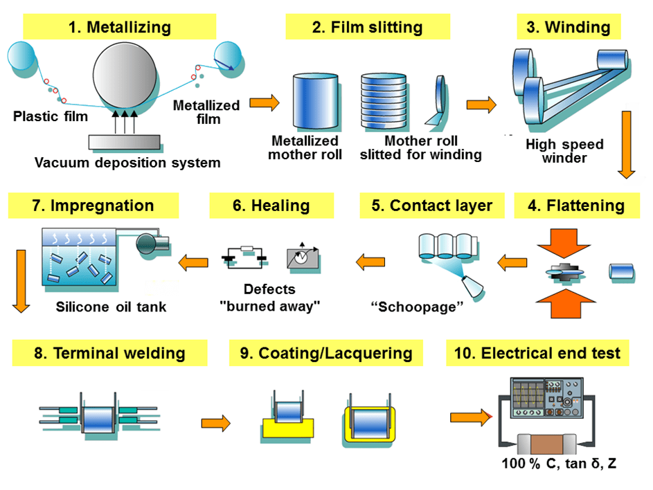
- Film stretching and metallization — To increase the capacitance value of the capacitor, the plastic film is drawn using a special extrusion process of bi-axial stretching in longitudinal and transverse directions, as thin as is technically possible and as allowed by the desired breakdown voltage. The thickness of these films can be as little as 0.6 μm. In a suitable evaporation system and under high vacuum conditions (about 1015 to 1019 molecules of air per cubic meter) the plastic film is metallized with aluminum or zinc. It is then wound onto a so-called “mother roll” with a width of about 1 meter.
- Film slitting — Next, the mother rolls are slit into small strips of plastic film in the required width according to the size of the capacitors being manufactured.
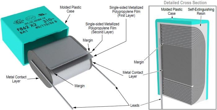
- Winding — Two films are rolled together into a cylindrical winding. The two metallized films that make up a capacitor are wound slightly offset from each other, so that by the arrangement of the electrodes one edge of the metallization on each end of the winding extends out laterally.
- Flattening — The winding is usually flattened into an oval shape by applying mechanical pressure. Because the cost of a printed circuit board is calculated per square millimeter, a smaller capacitor footprint reduces the overall cost of the circuit.
- Application of metallic contact layer (“schoopage”) — The projecting end electrodes are covered with a liquefied contact metal such as (tin, zinc or aluminum), which is sprayed with compressed air on both lateral ends of the winding. This metallizing process is named schoopage after Swiss engineer Max Schoop, who invented a combustion spray application for tin and lead.
- Healing — The windings which are now electrically connected by the schoopage have to be “healed”. This is done by applying a precisely calibrated voltage across the electrodes of the winding so that any existing defects will be “burned away” (see also “self-healing” below).
- Impregnation — For increased protection of the capacitor against environmental influences, especially moisture, the winding is impregnated with an insulating fluid, such as silicone oil.
- Attachment of terminals — The terminals of the capacitor are soldered or welded on the end metal contact layers of the schoopage.
- Coating — After attaching the terminals, the capacitor body is potted into an external casing, or is dipped into a protective coating. For lowest production costs some film capacitors can be used “naked”, without further coating of the winding.
- Electrical final test — All capacitors (100%) should be tested for the most important electrical parameters, capacitance (C), dissipation factor (tan δ) and impedance (Z).