
Supercapacitors – Basic Function & Construction
Supercapacitors are getting a lot of attention these days, lets overview its construction, technologies available and basic function. Please read the following article:
C 4.0 SUPERCAPACITORS
C 4.1. Introduction and Basic Function
Supercapacitors (or ultracapacitors) are the fastest growing capacitor technology on the market offering very high DC capacitance and high energy densities. Sometimes all supercapacitors are mis-called as EDLC (Electric Double Layer Capacitors), but as we will explain shortly, EDLC is large, but only one part of supercapacitor family. Supercapacitors features sit between capacitors and batteries, with a firm cell rated voltage between 1 and 3.8V. Since its introduction, supercapacitors has proved to be very reliable; with continuous long life operation and practically no charge/discharge cycle wear out.
Supercapacitors are used as DC energy storage media, short high power charge storage (automotive start-stop systems), back-up for semiconductor memories and microprocessors etc. New designs in larger modules have opened up space for a number of power applications that concur rechargeable batteries.
There is no fixed dielectric material and charge is accumulated in interface between active electrodes and the electrolyte. There are two basic mechanisms of charge storage:
- Electrostatic Charge Storage
- Pseudocapacitance Electrochemical Charge Storage
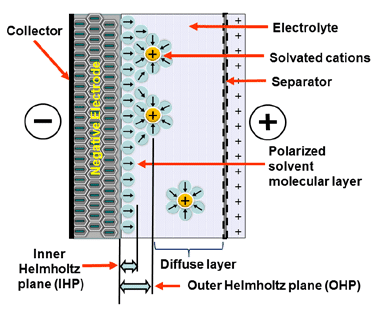
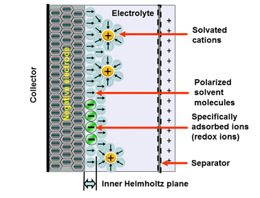
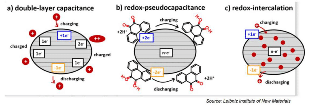
Electrostatic storage is based on accumulation of charge in charge traps within so called Helmholtz layers (inner and outer) – see Figure C4-1a. Pseudocapacitance storage is electrochemical process, where charge is accumulated by adsorbed ions. – see Figure C4-1b.
Mix of both charge storage mechanisms present in real supercapacitors. Per dominant charge mechanism supercapacitor types split in three categories as shown in Fig. C4-2:
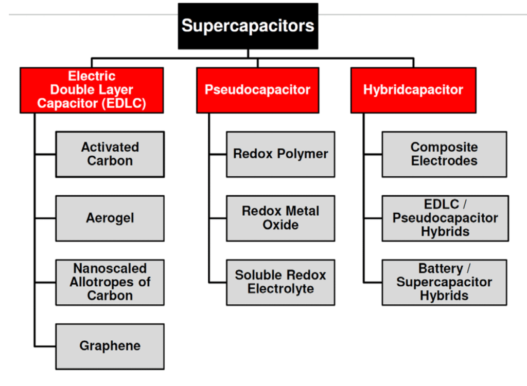
- EDLC Electric Double Layer Capacitors with electrostatic charge mechanism dominance
- Pseudocapacitors – electrochemical charge dominance
- Hybrid – one electrode with electrostatic and second with pseudocapacitance mechanisms dominance
EDLC capacitors are using high surface synthesized electrodes based on activated carbon, carbon nano-tubes or graphene. Alternatively, the electrodes can be made from cheap “bio-waste” monolithic material with a natural hierarchy of pore sizes such as coconuts, melon rinds, wood, fish scales etc.
EDLC capacitors with symetrical electrodes are non-polarized but are in practice supplied with a polarity marking that should be followed. One reason is that the positive electrode (+) may be processed differently from the negative one (-).
The electrochemical storage – pseudocapacitance – is not related to any electrochemical reaction – in difference to batteries. The charge can be stored by mechanisms such as redox-pseudocapacitance or redox-intercalation – see figure C4-3b and C4-3c below.
It is also possible to combine hybrid designs with other electrode technology such as
- capacitor hybrid: wet tantalum hybrid capacitor – one electrode tantalum anode and second electrode supercapacitors
- battery hybrid: supercapacitor one electrode and second battery electrode
C 4.2. Construction
C 4.2.1. Electrodes
Superacapacitor construction is explained on EDLC symetrical structure, nevertheless the basic design concept is also valid for pseudocapacitors that target boosting electrochemical storage using different materials, processes and electrolytes.
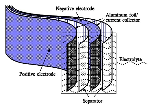
When we apply a voltage over the capacitor, existing ions in the electrolyte go through the membrane to their respective electrode, i.e., to the surface of the activated carbon that via the electrolyte is connected to the current supply electrodes. The ions are captured of the activated carbon surface where they attract reverse charges inside the carbon (Figure C4-4 and C4–5). We thus have a double layer of charges. Hence the name double layer capacitor. A schematic taken from a modern construction is shown in Figure C4-5. The original designs from 1970s used a membrane and conductive rubber as a current collector as shown in C4-4. In modern constructions membrane is replaced with a separating porous foil and the conductive rubber with a current collector, usually an aluminum foil – see Fig C4-5. Structure of wound – stacked type using aluminum foil as current collector is shown in figure C4-6.
Figure C4-4 illustrates how the activated carbon and the ions in the electrolyte work together.

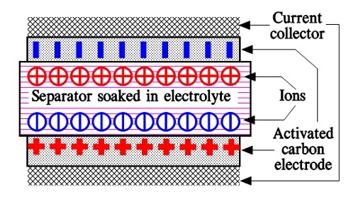
Because the distance between the charges is small – ion diameters – , and furthermore, because the total carbon surface is enormous the charge quantity will be extremely large. The capacitance range amounts to the magnitude of several thousand farads.
The continuous development to enlarge surface area has resulted in sophisticated active electrode system based on carbon active layer (carbon fibers), carbon nano-tubes (CNT) or the latest design with graphene.
C 4.2.2. Electrolyte
Applied voltage, efficiency and power handling also depends to selection of electrolyte. Electrolyte provide a media that supports creation of charge on interface with electrodes, enable its mobility or provide adsorbed ions as charge carriers (pseudocapacitance). Electrolyte matching with electrode system is thus essential to achieve both maximum energy and power density and also define its cell voltage.
There are currently three types of electrolytes:
- aqueous based
- organic based (liquid or solid/gel)
- ionic liquids
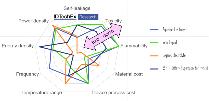
Aqueous electrolytes provide good conductivity at no toxity, however, maximum voltage reach 1.2 V.
Organic electrolytes are capable of maximum ~3 V and providing better temperature range, nevertheless they can be limited by flammability or toxicity. Solid organic electrolytes usually consist of conductive polymers characterized by low ESR values and corresponding power pulse capabilities.
Ionic liquids, the latest electrolyte development steps, are salts in liquid form rich on ions and short-lived ion pairs. This electrolyte enabled further increase of maximum voltage to ~3.7 V at no issue with flammability or toxicity – see spider chart benchmarking electrolyte types in Fig. C4-7.
If voltage is higher than the maximum cell voltage the electrolyte starts decomposing to form H2 and O2. Just below that voltage the surge voltage is specified and with some margins to the surge voltage we find the rated cell voltage.
C 4.2.3. ESR Resistance
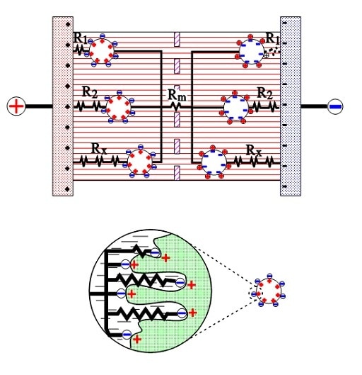
The active electrode (carbon) particles in the dispersion variant have via the electrolyte and via adjacent particles connection with the current supply electrodes. Some particles are situated close to its electrode and have a comparatively small contact resistance, others have long contact chains and manifold larger connection resistances. In Figure C4-8 three particles are shown with the series resistances R1, R2 and Rx, where R1 < R2 << Rx. The figure also shows the membrane resistance Rm in the electrolyte. The carbon particles are not spheres but have a surface with hollows and channels, just as the etched surface of an aluminum foil, but even more enlarged. See the schematic enlargement in the figure.
The electrolyte resistance from the inlet to the bottom of a channel will be considerable. The charges in the channel get a varying contribution of series resistances, depending on location in the channel, a contribution that shall be added to those resistances R1, R2…. , intimated in the entire view. This results in a multitude of elementary capacitances mutually connected in parallel in a complicated resistor network whose part resistances differ between themselves with a number of powers of ten. The time constants of the respective elementary capacitances varies from fractions of a second to hundreds of hours. The resistance network can be summarized to an ESR that varies with capacitance, type and manufacture from milliohms to several hundred ohms at RT. What contributes to the lower ESR values of modern ultracapacitors is the more conductive organic electrolytes or ioniq liquids as well as improvements in the contact medium between the active electrode particles and current collectors.
Because the ESR present in many backup capacitors is large compared to aluminum electrolytics it limits the ripple current use. A usual limit for the heat release is set to +2 °C.
Note that we don’t have any real dielectric, only a face boundary between electrode and electrolyte of 2 to 5 nm, that prevents respective charges from passing.
C 4.3. Series connection
Energy increase with voltage squared, thus modern high power electronics require work in 16, 25, 35, 50, 110 volt ranges, which requires multiple cell linking (2 to 4 V). The automotive market push towards 48 volt subsystems.
That raises concern about reliability of units containing multiple cells linked together. If we in electronic designs want to connect discrete capacitors in series to meet higher working voltages we should use the same type of elements.
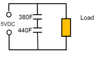
As an example: Series connection of 2pcs 400F 2.5V cells with +10/-5% cap tolerance in worst case scenario will end up with 380F and 440F caps on the board. The voltage of the individual cells will split accordingly to: 2.68 V: 2.32V that exceeds rated voltage of the first capacitor.
As noted from electrolyte decomposition, the rated cell voltage of supercapacitors (or surge voltage, if specified) must not be exceeded. Exceeding the maximum cell voltage considerably lower life time of supercapacitors, thus use of balancing circuits are strongly recommended when connecting unit cells in series to attain higher rated voltages.
Picked from a manufacturer datasheet: Rule of thumb by EDLC supercapacitor lifetime prediction is:
- With every 0.2 voltage decrease the cell lifetime increases about 2x in the specified voltage range
- With every 0.1 voltage increase over the spec V the cell lifetime gets half
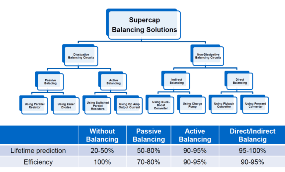
see figure C4-9. comparison of balancing methods and its impact to lifetime and efficiency.
If we don’t use external voltage dividers it is recommended as a precaution that the applied total voltage divided by the number of linked cells does not exceed 85% of the rated cell voltage.
Note: Low voltage (~1.8V) aqueous electrolyte type may not require balancing on higher voltage modules as the variability of applied voltage on high number of cells/layer may not be critical.
As mentioned in above, there are also available HYBRID designs
- capacitor – supercapacitor with one electrode made of conventional capacitor-type electrode (tantalum) and second as supercapacitor
- supercapacitor – battery – one electrode made as supercapacitor, 2nd as battery
Example of progressing battery-supercapacitor structure can be lithium-ion capacitor described in a technical article by Jianghai here:
Development of new supercapacitor technologies is progressing well, closing a gap to conventional batteries. One of promising directions is towards green, lightweight, lower cost high performance materials such as graphene. Research article example claiming record energy and power density can be found here.