
Basic Concept of Electrolytic Capacitors
The basic idea of electrolytic capacitor types is to maximize surface area of electrodes and thus increase its capacitance value and capacitance density.
Fine pores, cavities created on the electrode (anode) surface are then covered by a dielectric – usually insulator/semiconducting metal oxides. Electrolyte in a liquid/wet, gel or solid form is used as a media to contact the high surface from the second side and bring it by its electrical conductivity mechanisms to the second electrode (cathode).
This construction has a couple of advantages and limitations. Please read the following chapters:
C 3 ELECTROLYTIC CAPACITORS
Electrolytic capacitors are more complicated than electrostatic capacitors in their construction. The function of electrolyte is to provide electric connection to the first electrode with very high surface with fine structure and thus to achieve high capacitance values. The capacitors have an anode and a cathode and thus they are polarity dependent. Between the anode and the cathode there is a conductive medium in liquid or solid form called an electrolyte and that in practice serves as part of the cathode. The capacitors derive their name from the electrolyte and are in the everyday language called electrolytics. Sometimes tantalum electrolytics are abbreviated tantalums.
C 3.1 CONSTRUCTION
C 3.1.1 Capacitor Materials
The dielectric of electrolytic capacitors consists of oxides of aluminum (Al), tantalum (Ta) or niobium (Nb). They belong to the so called valve metals that have the characteristic of forming oxides with rectifying action by anodic oxidation. The basically formed oxides of aluminum, tantalum or niobium depends on the specific oxide state of the metal. Hence we get Al2O3 with an εr ≈ 8 – 9, Ta2O5 with an εr ≈ 27 and Nb2O5 with an εr of 41. Since other capacitor types are named after their dielectric also the electrolytics should have, by rights, been called oxide capacitors but the current denomination is too recognized to be replaced by anything else. Both the Al and Ta oxides have a good insulation capability and a very high dielectric withstanding voltage. Because these oxides can be made very thin we get, according to the formula C = ε x A/d a corresponding high capacitance.
C 3.1.2 Formation
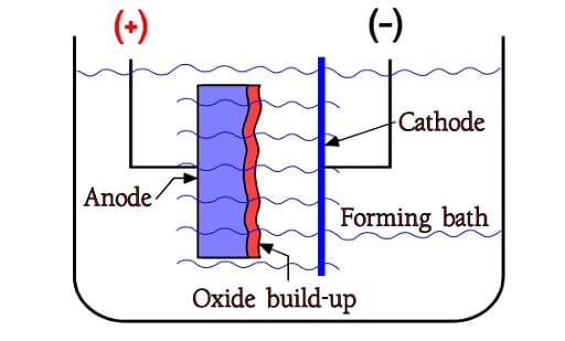
The oxides are formed already in free air but by supplying constant current from the metal into a so called formation bath it is possible to build up an oxide layer, however only to a certain limit. Figure C3-1 shows a forming bath or electrolyte with two electrodes, the positive anode and the negative cathode. The oxide build-up takes place on the anode metal, on the interface between electrolyte and metal. When the formation voltage for Al foils approaches certain limit values – presently approximately 800 V – we get to a limit where the oxide growth stops. A little way under that we find the maximum rated voltage for wet aluminum electrolytics, i.e. approximately 550 V.
Solid ones require, as we shall see, quite different margins to the formation voltage. For wet tantalum electrolytics with a foil electrode design the maximum rated voltage stops somewhere above 300V, for wet sintered styles at 250V and for solid sintered styles at 150V. The oxide build-up process is called formation or anodic oxidation and it continues until the applied formation voltage exceeds the required rated voltage to some extent. For wet electrolytics it is usual to stop some ten per cent above VR. Solid electrolytes, however, require formation voltages that are multiples of the rated voltage. Common to all electrolytics is their inability to stand considerable overvoltages. Whereas electrostatic capacitors are specified for test voltages at 150…250 % of the rated voltage, specifications for electrolytics state a surge voltage, Vs, usually 110⋅⋅⋅115 % of VR. The surge voltage is a maximum voltage of short duration.
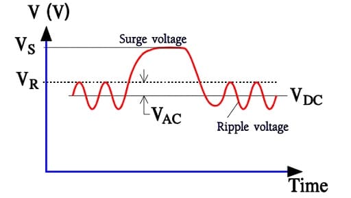
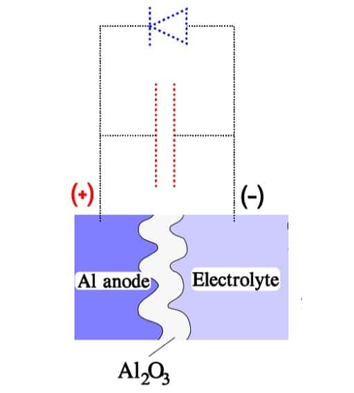
The sum of the working DC voltage and the peak value of the superimposed AC voltage, also called ripple voltage, must not exceed VR under continuous operations. Figure C3-2 shows a diagram with the rated DC voltage VR, the working voltage VDC, a superimposed AC voltage VAC and finally a surge voltage VS. The formation process is polarity-dependent. If we reverse the polarity the oxide layer will be decomposed. Schematically, the polarity-dependent oxide capacitor can be described as a capacitance connected in parallel to a diode.
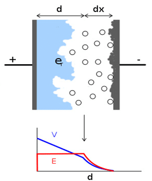
In the inverse direction of the diode the capacitor can stand the voltage that corresponds to the thickness of the formed oxide layer. It depends on the electron deficient electrolyte that has little capability of supplying any charges to the oxide layer. The electrolyte contains, however, plenty of negative ions, mostly oxygen, but due to their comparatively large size they can diffuse through the narrow oxide crystal grid only at a very slow rate.
Together with the sparsely occurring electrons in the electrolyte they constitute a small but not negligible current, the so called leakage current. In the reverse direction of the capacitor, however, electrons can move relatively freely from the anode metal through the oxide layer to the electrolyte where they meet a corresponding ion stream. The oxide layer conducts as a diode and the voltage drop will be correspondingly low (Figure C3-3). If we should apply a reverse voltage over the finished capacitor the leakage current will increase, in he worst case as an avalanche. It depends on the temperature, voltage and, not least, the type of capacitor.
Electrochemical oxide growth through formation can in principle be adopted to any low rated voltage, with start from the dielectric withstanding voltage of the air oxidized layer. This is approximately 3 V for tantalum and 1 V for aluminum. The aluminum oxide layer (Al2O3) then increases during the formation process with approximately 1.5 nm/V (0.06 microinches/V), the tantalum pentoxide (Ta2O5) with approximately 2.2 nm/V (0.09 microinches/V) and niobium pentoxide with approximately 25% more than the tantalum pentoxide. C
3.1.3 Surface magnification
As we can see by the formula C = ε x A/d the capacitance increases when the surface is enlarged. In electrolytics the surface is enlarged in either of two ways: 1. By etching plain foils, thus getting a rough surface. 2. By sintering together metal granules into a porous pellet whose summed up granule surface will be very large.
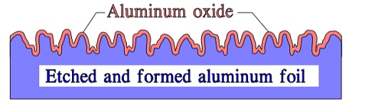
In principle etching may look like the cross cut in Figure C3-4. In reality it has a sponge or tunnel like appearance. It is made with a varying degree of penetration, surface character and surface magnification, i.e., how many times larger the etched surface is than that of the plain foil. Improved technology and means of control have on Al foils made an extremely high surface magnifications possible. Common figures talk of maximum 300 times. A nother source claim 400 to 1000 times.
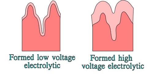
In high voltage electrolytics the hollows are reduced by the thick oxide layer. The surface magnification decreases (Figure C3-5).
The borderline between low voltage and high voltage electrolytics usually is set at VR ≤ 100 respectively ≥ 150V. The more decomposed the etched surface is the more important it is to rinse all pockets, cavities and ducts of the surface from the aggressive etching solution. The users must select those manufacturers that demonstrate a focused effort at achieving the degree of cleanliness necessary and that have the quality controls in place that check for adequate rinsing with every lot of parts.
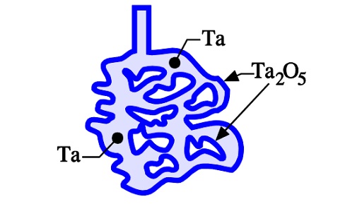
If we sinter a compressed pellet of tantalum or niobium/NbO powder we get a connected but porous metal core consisting of metal powder granules. The summed up surface of all granules represent a very large area compared to that of the compressed metal powder core. The tantalum or niobium/NbO compound then is formed and supplied with an oxide layer of required thickness. Figure C3-6 shows a schematic picture of the sintered and formed tantalum pellet.
C 3.1.4 Electrolytes
A capacitor consists of two electrodes separated by a dielectric. The rough or porous surface we have created by etching or sintering would be useless if we couldn’t make electrical contact to the whole surface. This is done by means of electrically conducting media, called electrolytes, which have the capability of penetrating all voids and ducts. Thus the electrolyte will be the base for the electric flux lines going from the anode metal through the dielectric oxide to the interface between oxide and electrolyte. Because the field lines always is orientated in a perpendicular direction to the “starting” and “landing” surfaces, every little surface element will be equally active, no matter where it is situated. Electrically the electrolytes represent the actual cathode in every electrolytic capacitor.
C 3.1.4.1. Wet electrolytes
Accordingly, electrolytes need good electric conductivity over the entire temperature range of formation and use. They should not attack the oxide layer and they should provide no damage to the environment either upon creation or disposal. Furthermore, they should serve as an oxide formation bath at the so called post formation process or aging, when small damage sites on the oxide layer that are created during manufacturing or testing are repaired. The tantalum pentoxide is extremely resistant to chemical attacks. It can, for example, bear concentrated sulfuric acid and because the sulfuric acid has manifested itself as a good conductor it is used in wet sintered tantalum electrolytics. Consequently, wet sintered tantalum capacitors must have a correspondingly capable and reliable seal.
Hermetic seal is a rule but there also are cheaper variants with squeezed elastic polymer (elastomer) seals. Liquid sulfuric acid would sometimes cause a certain capacitive position dependency which in some older national standards where limited to a ∆C/C of ±1%. Thus, the acid usually is given a gel-like consistency. In tantalum foil styles a paper foil separator is needed. Due to the reason that the necessary separator would be attacked by sulfuric acid other electrolytes must be used. The aluminum oxide is considerably more sensitive to various electrolytic liquids. Formerly solely water based glycol borates were used, with a water content of 20 – 30%. The water, however, attacks the oxide layer.
Should there be no voltage applied to the capacitor Al ions will dissolve and the oxide layer will gradually be consumed. If such a capacitor is suddenly connected to full rated voltage the leakage current will be high and a reforming will take place. That means that Al ions from the decomposition process again will be oxidized to Al2O3 and that hydrogen will be created in the form of gas. In the worst instance the creation of gas will be so great that the capacitor case will be ruptured. In any case it is the electrolyte that maintains the reforming process and that means that the electrolyte store will be consumed. The reforming process will continue until the oxide layer is built up to a thickness corresponding to the applied voltage. Then a state of equilibrium occurs where a small fraction of the normal leakage current will be requisitioned for a continuos slight maintenance formation that keeps in step with the decomposition rate. Also this maintenance formation consumes the electrolyte.
If the oxide layer should be damaged in a weak spot, for example by a voltage spike, we get a surge where the capacitor empties its energy through the short-circuit site. Has the circuit moreover a high impedance the short-circuit current will be limited and the damage stops with the momentary breakdown. Then the current, by means of the electrolyte, starts forming the surface of the damaged site until the foil damage is healed. We have thus a self-healing process. Latent damage sites may be caused by impurities in the aluminum oxide or by contaminants on the aluminum surface, for example chloride ions from perspiring hands.
The anode foil therefore should be as free from impurities as possible and needs for that reason a minimum purity of 99.99% Al. Handling of the “naked” aluminum foils must be executed with rubber gloves and the manufacturing, moreover, requires extensive automation in order to avoid contamination risks and gain uniformity in production. The aluminum electrolytic capacitor with water-based electrolytes can not withstand storage for more than a certain limited time that, depending on quality, can vary between ½ to 3 years at room temperature. Then it had to be reformed which should be executed with a current limitation of 10CV µA, where C and V are ratings expressed in µ F and volt. When the voltage over the capacitor has risen to rated voltage the formation can be regarded as completed. In order to eliminate the drawbacks associated with water based aggressive glycol borate electrolytes, even better electrolytes have been developed.
They have longer shelf life and a broader temperature range. Organic types are the best, with a water content of approximately 2 %. Storage shelf life at maximum 40°C exceeds 10 years. They are, however, more expensive and reserved for professional applications. As said before, there is one anode and one cathode in the electrolytic capacitor. In the aluminum electrolytic the cathode consists of an aluminum foil separated from the anode foil by a porous 40⋅⋅⋅90 µm (1.6⋅⋅⋅3.5 mils) thick paper foil. It absorbs most of the electrolyte liquid which means that the electrolyte store is considerably limited.
C 3.1.4.2. Solid electrolytes
These electrolytes are a solid substance that is electrically conductive and makes contact against the oxide layer of the electrolytic capacitor. The most common type are semiconducting manganese dioxide (MnO2) or conductive polymer organic material.
Manganese Dioxide (MnO2)
The capacitor is vacuum impregnated with a low viscosity liquid consisting of manganese nitrite and water. During a following pyrolysis process water and nitrous fumes evaporate. Left will be an adherent, thin crystalline layer of manganese dioxide with a good conductivity over a broad temperature range. Because the pyrolysis leads to a decrease in volume microscopic clefts are formed between the MnO2 layer and the dielectric oxide. The clefts reduces the capacitance yield and give the porous sintered tantalum powder complex a mechanically weakened structure. In order to fill the microscopic clefts the process of vacuum impregnation and pyrolysis has to be repeated together with a reforming that takes care of dielectric damage caused by the pyrolysis process. When used in sintered tantalum capacitors the course of events may, depending on quality, have to be repeated up to 20 times.
Due to the high temperature at the pyrolysis some damage is caused to the dielectric with growth of native thermal oxide with less electrical strength features. In consequence this limit the minimum rated voltage of the capacitors to effectively 4V (2.5V). In the solid electrolyte there is no ion current as in wet electrolytes. The leakage current consists exclusively of electrons or holes by Poole-Frankel (hopping) mechanism.
If the manganese dioxide is used in solid aluminum electrolytics, the pyrolysis process has to be limited to maximum 4 – 5 times. The aluminum oxide can’t stand any more treatments. SMD sintered tantalums account for the majority of manganese dioxide electrolytics with larger share of the market. There are, also, solid aluminum electrolytics.
With that self-healing through forming is excluded in the finished capacitor. No local short circuit at all is allowed. Therefore the margins between the rated and formation voltage are enlarged from tens of per cent for wet types to hundreds for solid electrolytes. Because of the limit for formation voltage, the maximum rated voltage for solid electrolytics will be the unassuming 50 V for aluminums and 100 V for tantalums. We recommend maximum 45 V for Al and 50 V for Ta. For this reason of voltage limitation Al MnO2 capacitors are not preferred compare to wet/polymers/hybrid versions that present on the market.
Conductive Polymer
The other variant of a solid electrolyte is the Polymer electrolyte. On the aluminum oxide of an etched and formed foil is applied an electrically very conductive polymer according to Figure C3-7. The polymer coating of the dielectric in a porous pellet of a sintered tantalum capacitor is formed by dipping the slug in a monomer solution followed by chemical or electrochemical polymerization. The original polymer capacitors can stand temperatures up to +105°C, nevertheless 125°C or even 150°C rated capacitors are already on the market from multiple vendors.
The conductive polymer has significantly reduced ignition of tantalum based capacitors and its robustness against current surges. In relation, recommended voltage derating is lower compare to the MnO2 types. Typically the derating is just 10% up to 16V rated capacitors and 20% for higher voltage tantalum capacitors. The maximum rated voltage was initially lower compare to MnO2 types, however with technology advancements its currently even higher compare to MnO2 types up to 75V available by multiple vendors and up to 125V by single source. In combination with lower derating the conductive polymer tantalum capacitors are offering wider range of potential applications up to 48/100V power supplies.
The capacitor ESR is some ten powers better than that of the rather decent manganese dioxide. A variant of the polymer electrolyte used is today mostly PEDOT that has a better temperature stability compare to the older design based on polypyrrole. A description follows also later on, in Section C3-7.
The technology challenge has been to address humidity stability, robustness to thermo-mechanical load (such as multiple high peak reflow assembly process) and high temperature stability. Under continuous development these issues have been step by step addressed, the capacitors are MSL 3 rated supplied in dry pack but capable to withstand lead-free reflow, automotive AECQ-200 requirements or even 150°C operating temperature range.
Conductive polymer process is more benign to the dielectric with lower exposed temperature during deposition that allows to form thinner and more reliable thickness of the dielectric, thus high quality and high capacitance polymer capacitors are available already from 1.8V rated voltage on SMD tantalum capacitors.
One construction design of aluminum electrolytics is also using semiconducting organic material TCNQ that is another version of solid electrolyte (OSCON capacitor type). The winding is impregnated at a relatively high temperature with a melt of the salt that at cooling is transformed to a solid form. The disadvantage is toxicity of the salt and these types are step by step replaced by conductive polymer or hybrid electrolyte versions recently.
C 3.1.4.3. Hybrid Electrolyte (wet and solid)
Hybrid electrolyte design is combining solid and wet electrolytes within one capacitor construction. This solution is used today on Aluminium electrolytic capacitors to leverage pros and cons from the electrolyte types.
Solid electrolyte – conductive polymer is applied in thin layer on anode, cathode and paper foil in order to improve ESR and conductivity. The structure is then dipped into a liquid electrolyte as in the case of standard wet electrolytic capacitors. See Figure C3-7a.
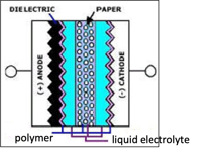
The hybrid Al electrolytic capacitors are currently growing its popularity, mainly in industrial and automotive applications. The hybrid design can achieve low ESR, high continuous ripple current values comparable with polymer types, while presence of the wet electrolyte is improving its DCL leakage current stability and resistance to thermal mechanical loads / reflow thermal stress.
C 3.1.5 The cathode
Cathodes in solid Tantalum, Niobium and Aluminum electrolytics
Solid electrolytes act in most instances as a cathode in the respective capacitor (Figure C3-7b).
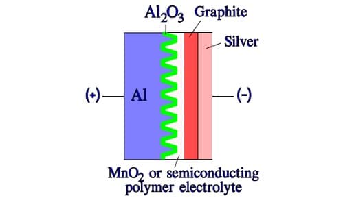
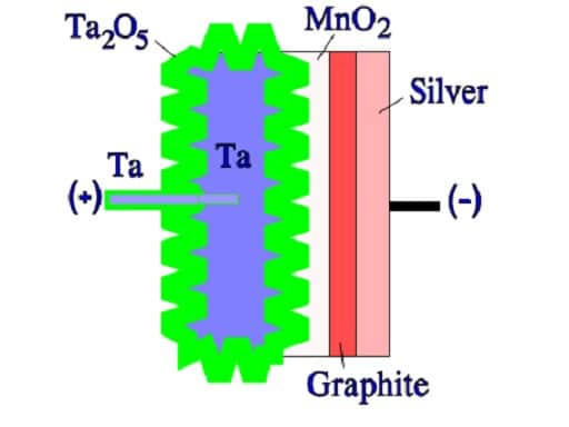
On top of the solid electrolyte a contact layer of graphite is then applied, followed by a silver-containing layer. To the silver layer is then soldered the terminal lead of the cathode. The lead of the anode side is welded if it is an aluminum foil. If it is a sintered tantalum capacitor the lead is inserted into the tantalum pellet and thus integrated with the core (Figure C3-8). Niobium is a nearby element to tantalum and its capacitor structure is identical to the tantalum – just niobium/NbO metal powder is used instead and the dielectric is Nb2O5.
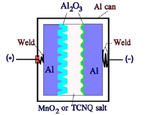
The most common design of the solid Al electrolytic has an Al can and a more conventional construction with both an anode and a cathode foil separated by a woven fabric. Also the TCNQ capacitor has the same fundamental construction but the foil separator consists of a carbonized paper foil (Figure C3-9).
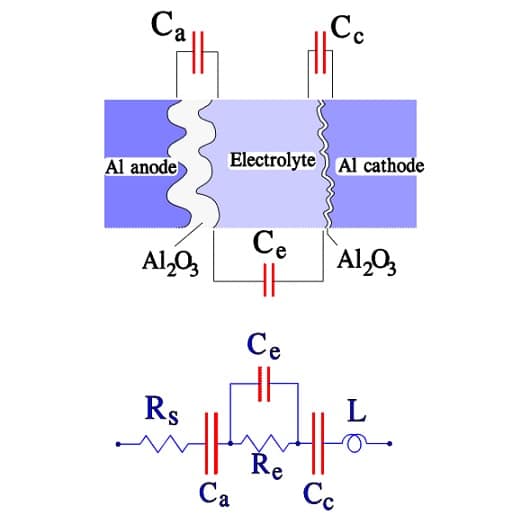
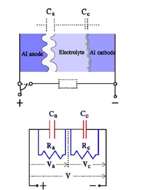
The cathode in a wet Aluminum electrolytic capacitor The cathode consists of an Al foil that formerly was plain but now has a certain degree of etching and subsequent surface magnification. It is not formed but has an air oxidized layer that corresponds to a voltage strength of approximately 1 V, which means that we have two capacitor elements connected in series. The construction and equivalent circuit may, with a certain simplification, look like the one in Figure C3-10.
Meaning of terms in Figure C3-10:
• Rs = losses in dielectric (oxide layer) and metallic conductive paths
• Re = resistance in electrolyte and separating foil
• Ca = anode capacitance
• Cc = cathode capacitance
• Ce = capacitance over the electrolyte
• L = inductance in winding and lead-in wires
• ESR = Rs+Re
• Cc >> Ca >> Ce
The capacitance of the thin cathode oxide layer is so large that it in series with the anode capacitance influences the total capacitance very little. Thus, the rated capacitance mainly is determined by the anode capacitance. Between the anode and cathode foils, directly across the electrolyte, a capacitance, Ce, is developed that at high frequencies will shunt the electrolyte resistance. Ce is at least two orders of magnitude smaller than the anode capacitance Ca. At a certain higher frequency 1/ωCe will be equally large as ωL. Left in the circuit then will be only Rs. The conditions are illustrated in the following impedance diagram.
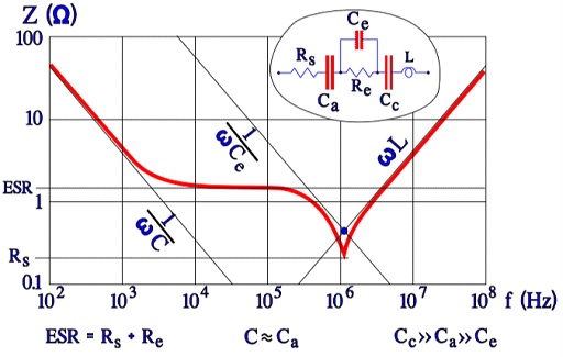
The diagram in Figure C3-11 shows that typical but strongly exaggerated dip around the resonance frequency where 1/ωCe = ωL; Z = Rs. In practice the minimum point is less pronounced, especially at lower temperatures where the ESR has higher values.
The cathode in a wet Tantalum electrolytic

The counterpart to the wet Aluminum electrolytic is the wet Tantalum foil style. It has plane or etched tantalum anode and cathode foils and uses a paper foil as a separator. Thus, aggressive electrolytes based on sulfuric acid that may attack the separator can not be used. Compared with the aluminum electrolytic capacitor it provides no obvious gain in capacitance per unit volume. In addition, because the price of this capacitor is relatively high and excellent competitors have been created in the aluminum electrolytics, this style part has no more use.
The wet sintered Tantalum electrolytic has a surface magnification that in combination with the wet electrolyte gives the largest CV product per volume unit.
The conventional design cathode serves a sintered tantalum sleeve inside the tantalum can (Fig.3-12 left). Thanks to the natural oxide layer of the cathode this type of capacitor can withstand reverse voltages up to 3 V without any risk.
High CV tantalum wet capacitor design without tantalum sleeve is available from multiple sources. The tantalum sintered sleeve is replaced with proprietary cathode with very high surface area (See Fig. 3-12 right). Elimination of the sintered cathode sleeve is enabling use of larger anode and thus higher capacitance volumetric efficiently. Disadvantage is in low reverse voltage allowance, usually 1V maximum. The tantalum wet electrolytic capacitors with sleeveless cathode (sometimes called “hybrid” – but not to confuse with aluminum hybrid electrolytics) achieve the highest energy density from all the electrolytic design. In combination with high power density, the tantalum wet capacitors has been the capacitor technology used for higher energy, high power devices such as implantable defibrillators or military radar applications.
The formerly common silver can cathode can’t stand any reverse voltage at all, not even momentarily. The risk of a short circuit caused by silver migration in addition is also the reason why silver can designs have been replaced by tantalum case in high rel applications.
C 3.1.6 Drawbacks with Surface Magnification
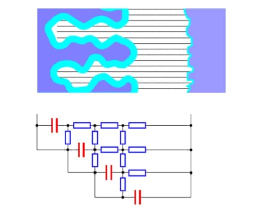
Unfortunately, the electrolyte has a nonnegligible electrical resistance. If we divide it in small contact strings towards the small surface elements of the oxide layer, the resistance of the conductive paths to the “peaks” of the etched surface will be small while the paths into the bottom of the ducts will be characterized by a high resistance. In diagram form it appears like the resistance network in Figure C5-13.
The time constant for the deepest situated capacitor elements will be considerably larger than that of the “peaks”. If we go from the farthest out located layer further in the ducts, successively more and more of the surface elements will quit when the frequency increases. Thus electrolytics have a strong frequency dependence. The higher the resistance in the conductive paths the larger will be the time constants for the elements and the stronger will be the frequency dependence. Because the electrolyte resistance is more or less strongly temperature dependent this will be reflected in the temperature and frequency dependence in a way we shall see example of in the description of characteristics for the different types.
C 3.1.7 Charge / discharge proof
If we apply a DC load on an Al electrolytic capacitor as shown in Figure C3-14, the voltage over the anode and the cathode will be distributed in proportion to respective insulation resistance, i.e. Va : Vc ≈ Ra : Rc. Because Ra >> Rc due to the corresponding dielectric thicknesses the voltage over the cathode will be small. Since the air oxidized layer over the cathode can withstand approximately 1 V in any direction it’s important to see to it that this voltage is not exceeded.
The charge distribution over anode and cathode can be described with Figure 15a that can be redrawn to 15b. If the anode and cathode should have same surface magnification, the surface unit capacitance [the specific capacitance] should be inversely proportional to the oxide thickness, i.e. Ra : Rc = Cc : Ca. But because the surface magnification is not increased as much on the cathode foil and because the conductivity over the cathode oxide is higher (it is loaded in its forward direction) we obtain Ra : Rc > Cc : Ca. Thus, Va : Vc > Cc : Ca; thence it follows that Va x Ca > Vc x Cc, i.e. Qa > Qc.
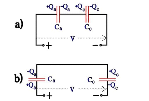
At short circuit over a low impedance load the charges will be distributed according to Figure C3-16a. The diagram can be simplified to Figure 16b
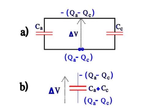
Over the cathode we then get a voltage ∆V = (Qa – Qc) / (Ca + Cc). If the voltage should be larger than 1 V the cathode successively will be formed at every discharge until Cc = Ca and the total capacitance C = ½ Ca. We have now developed a bipolar electrolytic that can withstand applied voltages equally well in both directions but whose capacitance is halved. A charge and discharge proof electrolytic should have the ability to withstand multiple voltage applications without reforming its cathode. Then its specific capacitance must fulfil certain conditions that can be deduced from the equations above. The better professional types usually are discharge proof but check before purchasing. IEC 384-4 specifies for charge-proof, low voltage electrolytics that when subjected to 106 charges and discharges of 0.5 s each with a circuit time constant of 0.1 s that capacitance changes can not exceed 10 percent.
C 3.1.8 Bipolar electrolytics ´Back-to-back´ connection
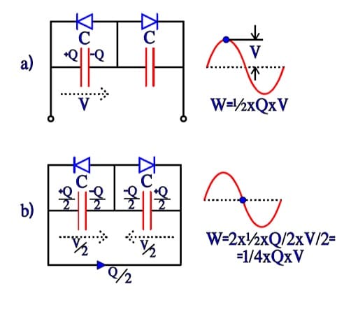
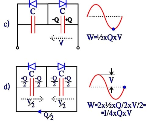
Bipolar electrolytics have, as mentioned before, two foils formed to the same voltage strength and equivalent otherwise. They can be described as two counterdirected and equally large electrolytics with their respective fictitious diodes connected in parallel over the capacitance C. If they are subjected to an alternating voltage we get the charge distributions and energy conditions shown in Figure C3-17, a through d. The energy W in a capacitor can be written W = ½ x C x V2 = ½ x C x V x V = ½ x Q x V. Thus the expressions in Figure C3-17.
Now, if we compare the differences in energy condition under an alternating current period, from a to b, from b to c, from c to d and from d to a, they will each time be ¼ x C x V2 = ¼ x Q x V. This value corresponds to an equivalent capacitor with the capacitance ½C. If the starting-point had been a polar electrolytic with the anode capacitance C, a formation of the cathode to same capacitance C would result in a total capacitance ½C, just as in a common series connection. If we on the other hand apply a DC voltage we get the same change of energy as the one under the first quarter period with the AC voltage, i.e., ½ x C x Q. It corresponds to a capacitance C over the active capacitor element, just as in the polar case.
Back-to-back connection
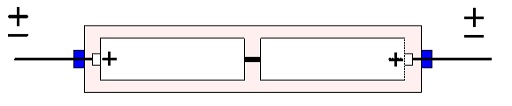
A variant of the bipolar electrolytic capacitor is often found in solid tantalum devices. It is based on the back-toback connection. Equivalent polar capacitors are matched together by the manufacturer and placed in a common tube where the cans and cathodes are soldered together (Figure C3-18). This design, however, is getting more and more unusual.
C 3.1.9 Mounting
Electrolytic capacitors are found in sizes from small SMDs to large can styles with clips or bolt mounting in panels. For mounting on PCBs there exist, except for axial or radial two-terminal components, also snap-in designs with two or several bent springy guiding sheets that sometimes also act as terminals, sometimes have only the guiding function.
The component leads are pressed down in the corresponding holes in the circuit board and the terminals are soldered to the plated via holes. Because of their size SMD styles always must be furnished with flexible J-leads in order to prevent damage during temperature cycles.