
Insulation Resistance, DCL Leakage Current and Breakdown Voltage
Another important features of every capacitor are:
- its ability to keep the charge for some time without self-discharging due to its internal leakage (conductivity) mechanisms. This is characterized by either IR Insulation Resistance or DCL leakage current electrical parameters. These are reciprocal parameters describing the same capacitor stage, so it does not matter which of those parameters is used. Electrostatic capacitors such as paper, organic film or ceramic capacitors are usually characterized by IR values, while electrolytic capacitors (aluminum, tantalum) with low IR values are using DCL leakage current specification instead.
- withstand a voltage before it breakdown. This is defined by its maximum Operating Rated Voltage and Breakdown Voltage. Rated voltage is a common parameter that you can find in catalogues and it practically means that manufacture guarantee the specified electrical parameters and reliability are maintained up to this voltage. The maximum rated voltage can be categorized by AC/DC operation or maximum allowed operating temperature (so called Category Voltage – will discuss this in next lectures)
C1.2 INSULATION RESISTANCE, IR

The dielectric of a capacitor has a large area and a short length. Even if the material is a good isolator there always flows a certain current between the charged electrodes (the current increases exponentially with the temperature). This leakage can be described as a parallel resistance with a high value, an IR Insulation Resistance (Figure C1-10).
Depending to the capacitor type you can find IR value or DCL specifications with reference to a standard conditions in manufacturers’ datasheets and catalogues. Electrostatic capacitors (film or ceramic) are using IR parameter while for electrolytic capacitors with their relatively low IR rather the DCL leakage current is specified.
C 1.2.1 Measurement of the IR and DCL
At an IR determination one measures the DCL leakage current through the capacitor. The measuring circuit, however, always contains a certain series resistance.
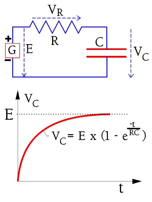
Hence we need take into consideration the charging time. The circuit diagram and charging curve for a capacitor are shown in Figure C1-11.
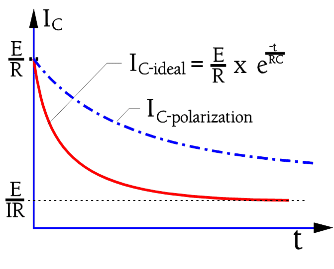
The charging current to the capacitor is shown in Figure C1-12 (circuit diagram as in Figure C1-11). If the capacitor were ideal the current would rapidly attain the limiting value corresponding to the IR. The ideal current curve is designated IC-ideal. But because the polarization in the dielectric requires a finite time for dipoles to reorient the real charging current follows the curve IC-polarization.
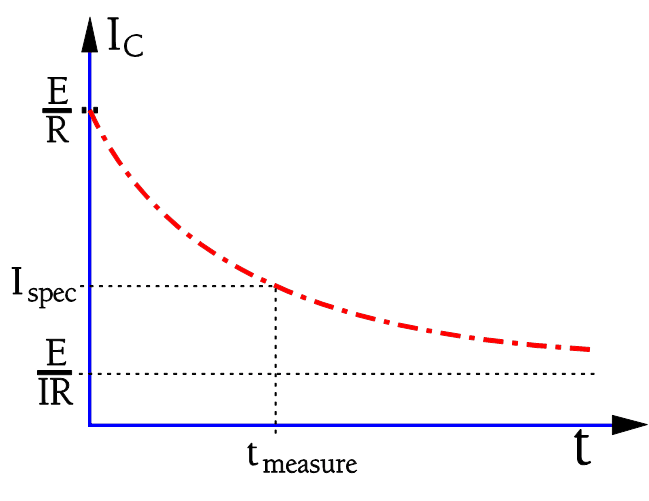
In order to attain the actual IR we would need to wait for a very long time. In practice we content ourselves with a specified IR value corresponding to a measuring current at the time tmeasure in Figure C1-13.
Here we have marked a specified current value which on the measuring devices are graded in the corresponding IR value. A common time for IR readings is in IEC specifications 1 or 5 minutes depending to capacitor type. The MIL specifications often call for 2 minutes or more.
Considerably shorter times are applied at incoming and production inspections to enable fast measuring in volume production. IR/DCL concerns the ”room temperature condition” (RT), approximately 23 °C. The IR decreases and DCL increases with an increase in part temperature and may, at the maximum temperature, be several 10 powers than at RT.
The IR of capacitors of a specific type and voltage rating decreases proportionally to the growth in capacitance (i.e., the increasing area). And vice versa. A reduced capacitance by a correspondingly lessened area will increase the IR. However, up to a specific maximum value of capacitance the IR actually is so high that it’s actually the outer construction and the molding or conformal coating that determines measured values. Above this breakpoint the specifications call for the constant product of IR x C (in seconds). This product also is designated the time constant (see next section).
C 1.2.2 The time constant
If we leave a charged capacitor with open connections the charge successively will leak from one electrode to the other through the internal insulation resistance. Eventually the voltage will drop to zero. Because of the very high IR of the electrostatic capacitor (non electrolytic) a complete discharging will take an extremely long time.
A more comprehensible measure of the discharge speed is the time constant. It is defined as the time for the initial voltage E to drop to the value 1/e by E (Figure C3-14).
With reference to Figure C1-11 and -12 we can define as the product IR x C. This quantity is deduced from equation (C1-1) as Ω x As/V = Vs/V = s(econds).
Periodically one sees the expression ohm-farad (ΩF) or the somewhat awkward megohm-microfarads (MΩF). Instead of using the expression IR x C it’s customary to mention only the RC product of the capacitor. Then R is understood as IR, i.e. IR x C = RC = τ .
τ = RC (s) or (ΩF) ………….[C1-8]

C 1.2.3 Dielectric Withstanding and Breakdown Voltage
The dielectric strength of the material is determined by the breakdown voltage and is expressed in kV/cm. As time, temperature and other factors determine the breakdown voltage this is reflected in conditions for measurements of the dielectric withstanding voltage, DWV. They are performed at a specified temperature, material thickness, frequency and shape of test voltage curve as well as connection method. DWV usually is determined as an average value of set of samples due to the effects of material variations etc.
Corona voltage
A practical and important limit for the breakdown voltage, especially in high voltage organic film or aluminum wound capacitors is the corona voltage, i.e. that voltage where corona starts appearing. Corona is initial electrical discharges in gases which then are ionized. The ionized products in air or in carbon-rich environments, typical in all microcavities or voids in the dielectrics as well as in large cavities within the component package, consist of ozone and nitrous fumes. Most organic dielectrics are directly affected by degradation. If the gaseous products have been created within a hermetically-sealed package as their concentration
increases they will degrade the behavior of organic dielectrics. Remember that AC peak voltages just above the corona voltage every half-cycle give a new contribution to the corona products. Additionally there is a heat release from the corona phenomenon which further accelerates the chemical decomposition.
On the whole there is a certain smallest field strength
needed in the cavity in order to start ionization. Moreover the ionization gap length comes into play. But even if the field strength according to the formula C1-6 should be considerably higher in one part of a mixed dielectric AC voltages below 250 V R.M.S. are harmless also in the most unfavorable case. On one condition: No incoming transients should be allowed that otherwise might start an ionization course of events. Hence we ought to create safe margins based on our knowledge of occurring transients. If unsure, one should use capacitors where the voltage is distributed over elements connected in series.
Transients and anomalies in the dielectric are a dangerous combination.
The following example will demonstrate the danger:
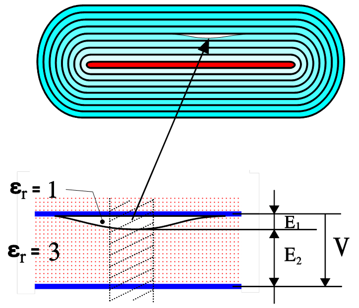
For the sake of simplicity the measurements and dielectric constants are chosen as in Figure C1-15. From formula C1-6 we obtain
εr1 x E1 = εr2 x E2; 1 x E1 = 3 x E2; E1 = 3E2.
Here we unintentionally have got an electric field strength 3 times the rated one. ”Safe” rated AC voltages just below 250 V or incoming transients certainly will start corona in such a void.
In high voltage ceramic capacitors intended for high reliability systems a testing and screening technique is used to detect voids and delaminations by evoking partial discharges (corona). The method uses preferentially AC
voltages just above the corona inception voltage (CIV) and is able to detect voids exceeding EIA-469 size requirements.
Test Voltage
The test voltage is a practical guarantee value of the capacitor. It is positioned well below the corona voltage and is applied for a specific limited time, e.g. 2 seconds at production control and 1 minute at type tests and incoming inspection.
Common test voltages may be 1.1xVR, 1.3xVR, 1.5 x VR, 2 x VR and the like depending to a capacitor type.
Capacitor Breakdown Types
There are two basic types of capacitor breakdowns:
(I) Electrical breakdown
During electrical breakdown, electrical field, usually related to excessive voltage applied, exceeds the electrical strength of the dielectric material resulting in complete disruption and low resistance / short circuit failure mode. The responsible conductivity mechanism is mostly tunneling of electrons or holes accelerated by electrical field over the critical value. An avalanche effect may then lead to a complete destruction and catastrophic failure – short circuit of the capacitor.
Critical specification parameters are: Rated AC/DC Voltage, Category Voltage (maximum voltage at defined temperature).
(II) Thermal breakdown
During thermal breakdown electrical field is lower then a critical value (applied voltage lower then rated voltage), but excessive current is flowing through the capacitor – either as high ripple current, transient current or in reverse mode (polarized capacitors). Joule heating caused by passing current increase local temperature inside of the capacitor structure up to a thermal damage and disruption of its materials.
Critical specification parameters are: Maximum ripple current/voltage; Maximum power rating; Maximum dV/dt or dI/dt transient or minimum series resistance of the circuit.
Electrical Breakdown Test
Capacitor electrical breakdown value may not be such exact parameter as one could expect. The critical parameter is applied electrical field on the dielectric but apart of the ambient temperature the state of the dielectric / energy dissipation may also depend on time and history (inner temperature due to past events, moisture etc).
for electrical breakdown we can consider the following test procedures that in some capacitor technologies may give different breakdown voltage values:
1] Static Breakdown
On external power supply we set-up maximum of current limitation and then increase voltage from rated voltage by small increments to minimize transient current until breakdown occurs. This can be done manually but, of course, it is better to do by more sophisticated programmable power supply or even automatic breakdown measurement systems that preciously detect the BDV voltage by change of dI/dt.
2] Dynamic Breakdown
During dynamic breakdown high power pulse is applied to the capacitor through low series resistance. Caution: the circuit has to reflect the maximum transient voltage/current limitation conditions not to cause thermal breakdown.
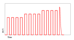
The test sequence is usually automated that we apply certain amount of pulses at desired voltage (such as 1.1xVr) and then if the capacitor survives we move to one step higher voltage ( for example 1.2xVr) until the breakdown of the capacitor. … again this can be fully automated using programmable power supplies.
3] Self-healing Suppressed Dynamic Breakdown
This test is identical to the dynamic breakdown as above, just the change is that we will replace the samples after each voltage step. This is relevant for capacitor technologies with self-healing as we want to suppress capacitors’ ruggedisation by self-healing process in previous load step. Target is to get the impression about its BDV robustness when uneven spike happens in real operation (without any conditioning by ageing) .
Differences between the BDV induced by above methods depend to the capacitor technology. There would be practically no difference on air/vacuum capacitors, little on electrostatic capacitors and more remarkable on electrolytic capacitors with self-healing where obviously the Static BDV > Dynamic BDV > Dynamic Breakdown without history