POLYPROPYLENE CAPACITORS PP / KP and MKP
C 2.4 POLYPROPYLENE (PP) / KP and MKP
In the book we use the common European abbreviations KP for film/foil and MKP for metallized film.
C 2.4.1 Introduction
Polypropylene (PP) is from a molecular point of view a non-polar dielectric with small losses and a relatively straight and moderate TC. Since the smallest film thickness is approx. 3.5 μm (0.14 mils) and εr ≈ 2.3 the capacitor can not come down to those sizes characterizing PET at low rated voltages. But remaining good characteristics in many applications have brought up PP as a replacement for polycarbonate (PC) and polystyrene (PS), not least as a precision capacitor. PP exists in both foil and metallized design and is adopted for both AC, pulse and transient suppression (X-capacitor) applications. The pulse and X-capacitor designs, however, require a specific metallizing technology.
The MKP design had from the beginning problems with the adhesion between the metallized layer and the plastic film. This problem characterizes non-polar dielectrics consisting of molecules and has caused many problems at, for example, gluing of components to circuit boards. The plastic surface film has to be raised and roughened which among other things can be done by etching, flame exposure, electron irradiation or corona. Today the MKP design is well established and the adhesion problems a passed period.
The demand for filtering / interference suppression of thyristor generated noise voltages has brought forth the same type of large capacitors as shown for PET but here the low ESR losses allow quite different r.m.s. currents, for example at high frequencies.
The recommended absolute maximum temperature is +105°C. We recommend max +85°C with the remark that developments of new films is going on to offer temperature range above +105°C as a maximum operating temperature. Current temperature limitations still make PP difficult for chip designs.
C 2.4.2 Temperature and frequency dependencies
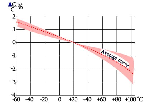
Figure C2-45. Typical curve range for capacitance versus temperature of the KP and MKP design.
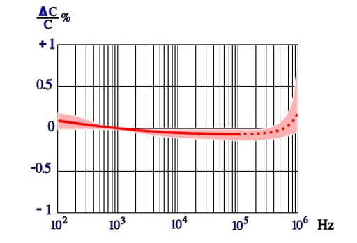
Figure C2-46. Typical diagram of capacitance versus frequency for KP/MKP designs.
The frequency dependence of capacitance for PP capacitors is moderate. In Figure C2-46 the broken part of the curve indicates an increase of capacitance. This increase is not physical but depends on influence from series capacitance measurements according to Formula C1-10.
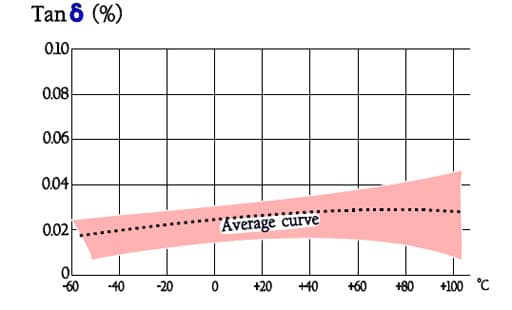
Figure C2-47. Typical curve range of Tanδ versus temperature for MKP and KP.
Note in Figure C2-47 the outstanding low loss factor for PP over the whole temperature range.
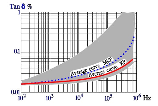
Figure C4-48. Typical curve range of Tanδ versus frequency for KP and MKP capacitors.
The curve area in Figure C2-48 represents capacitance up to some hundreds of nF. The higher capacitance, the greater losses.
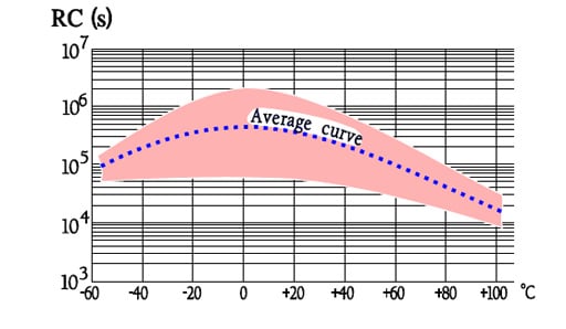
Figure C2-49. Typical curve range showing the IR versus temperature for KP and MKP capacitors.
Designs with foil or hermetic seal have somewhat higher IR than corresponding metallized and plastic encapsulated types.
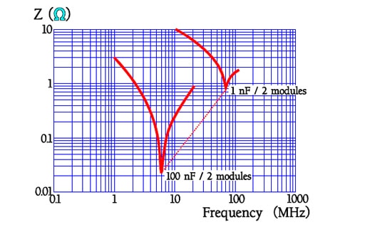
Figure C2-50. Examples of resonance frequencies for 2 modules lead space MKP capacitors.
C 2.4.3 Failure modes
Any characteristic failure mode just for PP capacitors is not distinguishable. Here what was said about PET usually applies.
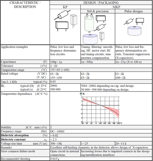
Table C2-5. POLYPROPYLEN (PP) / KP / MKP