
Variable Capacitors – Construction & Features
Variable capacitors are used for trimming and tuning function in electric circuits.
C5. Variable Capacitors
Variable capacitors are used for trimming and tuning purposes. They represent a small but important part of the capacitor assortment.
C 5.1. GENERAL DESCRIPTION
By means of an electrode system consisting of one fixed and one movable part – stator and rotor – the capacitance can be varied between a minimum and a maximum value, the so called capacitance swing.
The temperature coefficient (TC) for the different occurring dielectrics usually differs considerably from the corresponding values for fixed capacitors. The variations are, except for what applies for the best precision components, considerably larger which has to do with the mechanical conditions that the whole construction is based upon.
Trimmer capacitors are mainly designed for mounting on printed circuit boards (PCB) but surface mount designs are getting more and more common. Trimmers often have a friction that increases the turning moment and thus locks the capacitor in its adjusted position.
C 5.1.1. Turning types
Air dielectric
The classic variable capacitor consists of semicircular electrodes that can be turned into each other as shown in Figure C5-1. The styles are intended either for PCB or panel mounting. They are used preferably for tuning of resonance circuits.
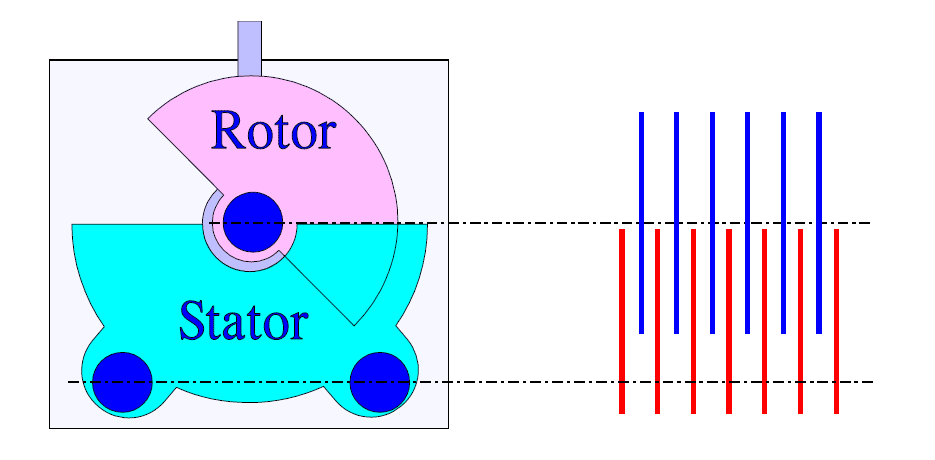
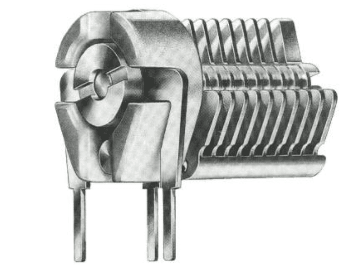
Figure C5-1. Schematic of a variable air-insulated capacitor and an example of Tronser’s make.
The air-insulated electrodes put great demands for mechanical precision. The plate distance usually is 0.2 to 1 mm. The price is relatively high.
Ceramic trimmers
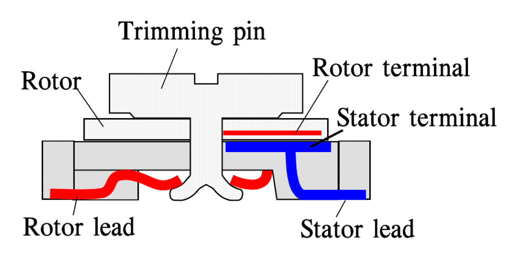
If we reduce the plates in Figure C5-1 to only one silver plated ceramic rotor that is turned in over the stator electrode we have got a ceramic trimmer capacitor. An example of this design is shown in Figure C5-2. Multilayer designs also exist. The capacitor styles are designed for either hole mount or surface mount.
Because Type 1 ceramics are used the losses will be relatively small.
Plastic foil types
If we exchange the air insulation in Figure C5-1 for some plastic foil the electrode distance can be decreased contemporaneously as the εr – and thus the capacitance, – increases, unfortunately to the trade off of a somewhat poorer Q value. Low loss plastics like teflon (PTFE), polypropylene (PP) and polycarbonate (PC) are common but also polyester (PETP) exists.
C 5.1.2. Concentric design
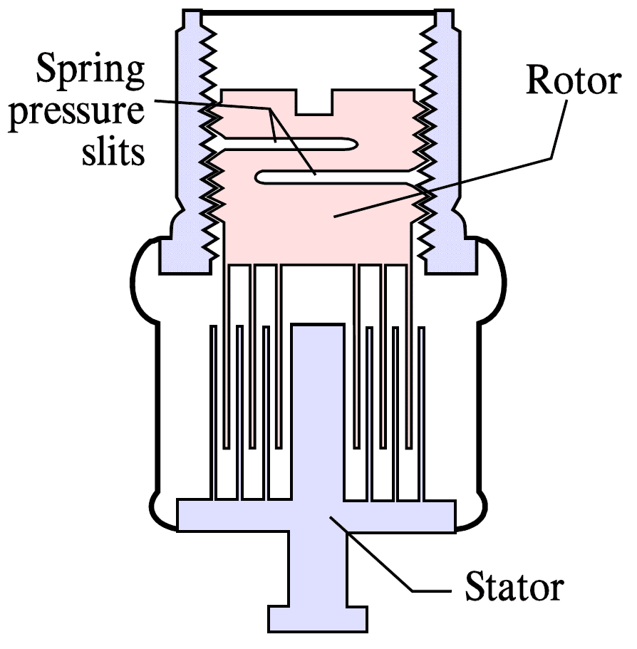
In the concentric type air usually serves as dielectric. Rotor and stator are made from, for example, gold-plated brass. The concentric type consists of concentrically-orientated metal tubes on both the movable rotor and the stator.
They are inserted into each other from the rotor side and are separated from each other by an air gap. It is a matter of precision design that permits air gaps down to 0.1 mm (4 mils). The Q value will be high and the dimensions comparatively large. The temperature coefficient is very small.
In order to get a setting stability one manufacturer uses one or several slits in the rotor that with spring force increase the friction and lock the trimmer in the adjusted position.
C 5.1.3. Piston design
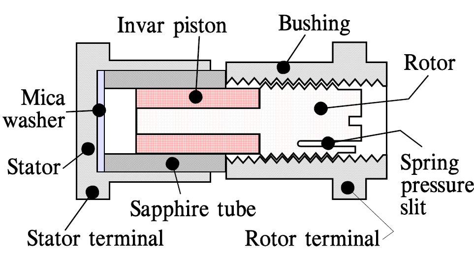
The piston design is used with air, teflon or sapphire as dielectric. With an εr of approximately 8 the sapphire dielectric achieves a certain capacitance per volume gain. Both hole and surface mount exist. A cross section through an SMD design with sapphire dielectric is shown in Figure C5-4. As for the concentric design the TC will be small.
C 5.1.4. Remarks
Trimmers for commercial use sometimes lack satisfactory encapsulation. Then they must not be washed or exposed to solder fluxes or cleaning solvents. Encapsulated types with plastic housings should not be exposed to trichloroethylene.
C 5.1.5. Failure modes
Just as with potentiometers, variable capacitors are electromechanical creations with a correspondingly high failure rate. The contact resistance to the rotor can vary and produce contact disturbances.
Contamination – not the least from flux cleaning – may cause similar problems. Contamination and corrosion of mechanical parts may occur. Short circuits due to severe mechanical misalignment of air insulated parts are reported.
Table C 5-1. VARIABLE CAPACITORS / TRIMMERS
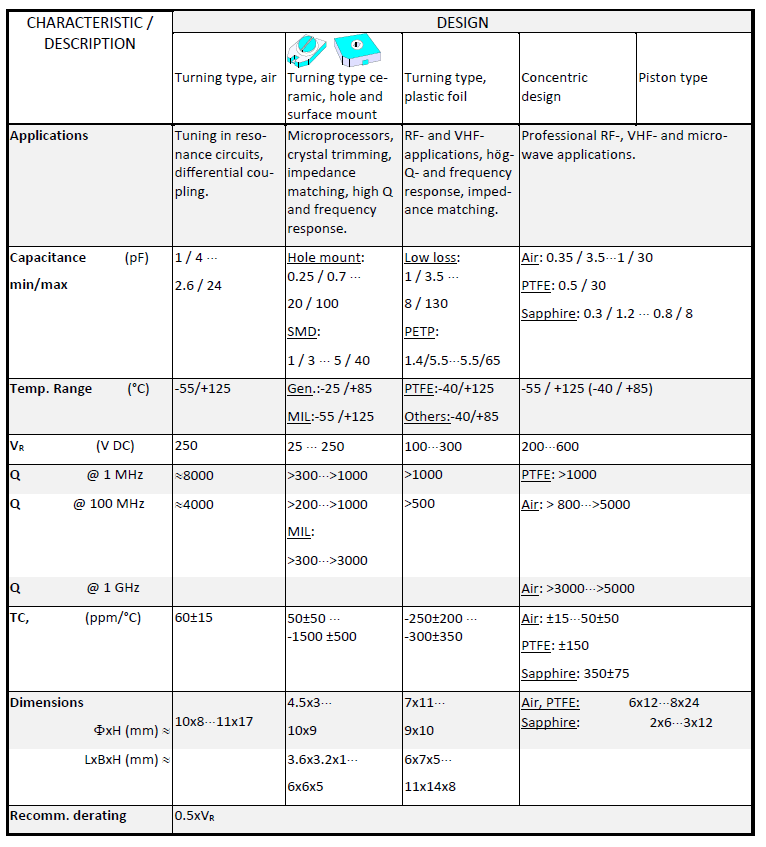
(The table shall be regarded as an orientation only. Stated limits may vary further.)