
Wet Tantalum Capacitors
Wet tantalum capacitors use a liquid electrolyte in their cathode hermetically sealed systems.
These capacitors offer the highest energy density among the classical capacitor technologies. The liquid electrolyte provides a continuous self-healing action for the dielectric, leading to low leakage currents, high reliability and a higher range of applicable operating voltages. Due to the resistance of the liquid electrolyte however, the ESR of most wet tantalums is not particularly good, resulting in loss of capacitance at relatively low frequencies. Wet tantalums are also quite costly, roughly 100x that of an aluminum electrolytic device of comparable ratings. Taken together, these factors render wet tantalums something of a niche technology, found mostly in the sort of applications where failure is not an option and money is not an object; medical implntable, space/satellite applications, life-critical avionics systems, etc.
C 3.8 WET TANTALUM ELECTROLYTICS
C 3.8.1. Introduction
Wet tantalum capacitors have several advantages over solid tantalum, aluminum electrolytic, and ceramic capacitors. As with all other capacitors, these advantages lead to a very specific “sweet spot” or focused area of applications where the wet tantalum capacitor is the best and preferred choice. Wet tantalums require little derating and offer higher voltages (75 V, 100 V, and 125 V) than solid tantalums.
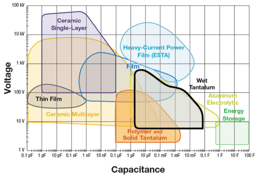
Rating for rating, wet tantalum capacitors tend to have as much as three times better capacitance / volume efficiency than aluminum electrolytic capacitors. Wet tantalums, with their hermetic case designs, have very long life and low DC leakage. Fig. C 3-64 below shows where the wet tantalums falls within the capacitor families. As shown, they offer higher capacitance and voltage than solid tantalums, but smaller size than aluminum devices with the same rating.
As we already have indicated there are two most common designs of a wet tantalum electrolytic with different cathode design: the sintered case and the proprietary cathode design style. In history there were one more style – foil tantalum wet capacitor that existed either with a plain or an etched anode foil. Because this design was expensive, relatively unusual and normally can be replaced with a wet aluminum electrolytic we will just mention its existence.
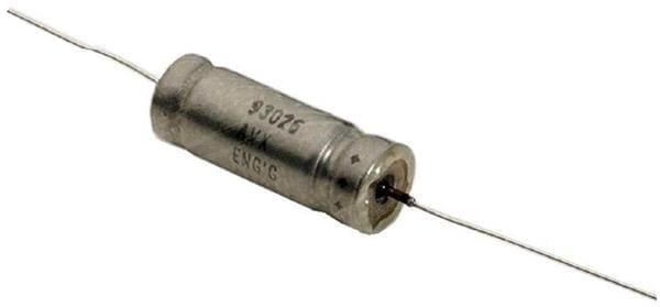
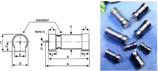
A typical construction of a sintered designs with a tantalum case MIL-C-39006 (left) and proprietary cathode DLA 93026 (rigth) may look like the one in Figure C3-65.

The wet sintered tantalum electrolytic with proprietary cathode system has the highest CV product per volume unit of all polarized electrolytics. In the first hand it depends on the formation voltage that, compared to solid tantalums, is approximately three times lower. This means that the corresponding dielectric thickness of a certain rated voltage will be only one third of that for the solid one and the capacitance three times greater. Thus, the solid tantalum capacitor needs a surface three times larger than that of the wet one for getting the same capacitance.
The wet sintered tantalum capacitor also has the lowest leakage current of the electrolytics. It is comparable with that of paper capacitors.
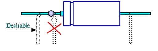
Exactly as with solid tantalums the density is so high that lead mounted types should be attached mechanically against its substrate.
The electrolyte consists of concentrated sulfuric acid. Therefore, the weld between the connecting nickel lead and the tantalum lead from the sintered core is placed outside the can. The lead must not be bent inside the weld. Otherwise the risk is high that the seal is dam-aged and sulfuric acid leaks out.
The sulfuric acid has a freezing point of approximately –64 °C. Its liquid state may sometimes give the capacitance a certain position dependency. This dependency is often avoided by giving the sulfuric acid a gelatinous consistence. The gelled electrolyte also is favorable with respect to the leakage risk.
The sintered wet electrolytic still is manufactured in a variant with silver can. The risk, however, of silver dendrite formation that causes a short-circuit is relatively high and tantalum case is the preferred designs. The conventional tantalum cathode sleeve design as per MIL-C-39006 style (Fig 3-65a left) is limited by CV but it can stand a reverse voltage of 3 V up to 85 °C. The proprietary cathode design type as per DLA 93026 is offering significantly higher capacitance range and energy density but no reverse voltage is allowed.
The following series of diagrams are applicable to both Ag and Ta case styles if nothing else is said.
C 3.8.2 Properties
Capacitance versus temperature
As other wet electrolytic capacitors also the wet tantalum has a strong temperature dependence of capacitance. It depends on the rather high resistivity of the electrolyte, especially at lower temperatures. This resistivity is, compared to solid electrolytes, high also at room temperatures which in turn is reflected on the presented frequency dependence measured at normal conditions. Figures C3-67 and –68.
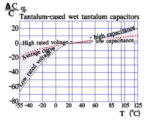
The temperature dependence of silver-cased wet tantalums have a slightly broader curve range for low rated voltage and high capacitance values.
Note in Figures C3-67 and 3–68 that “high rated voltage – low capacitance” constitutes one of the limits of the curve range and “low rated voltage – high capacitance” the other limit.
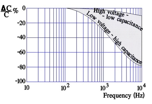
The fine powder technology is a condition for the low voltage – high capacitance styles. The high porosity of the pellet, however, increases the ESR of the electrolyte due to the electrolyte filled ducts that are becoming longer and finer and more resistive. The capacitance elements farthest in the pellet consequently require longer time constants for charging. When the frequency increases these elements become ineffective, i.e., the capacitance decreases with frequency (Figure C3-68).
Capacitance versus frequency
ESR versus temperature
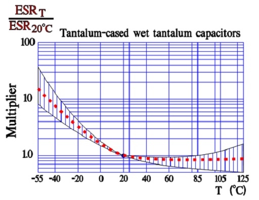
ESR in silver-cased tantalums differs slightly from tantalum-cased tantalums by having a broader curve range at higher temperatures.
The curve range in Figure C3-68 demonstrates a greater temperature dependence at low temperatures where the viscosity and resistivity of the electrolyte increase, more the higher the pellet porosity is. Conse-quently, at lower temperatures the upper limit of the curve range belongs to high capacitance designs.
ESR versus frequency
The frequency dependence of ESR is presented in a normalized form, i.e., as a ratio between the ESR at different frequencies and at 120 Hz .
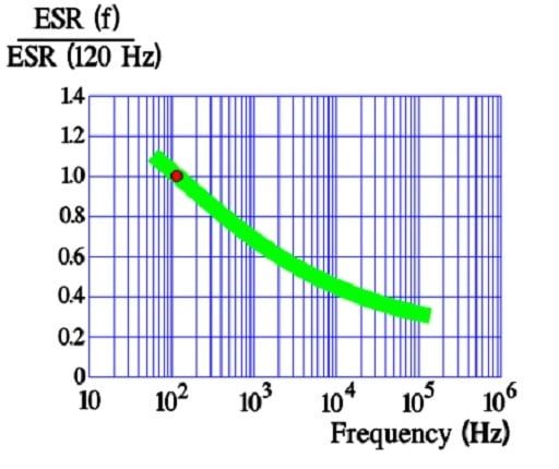
Compared to solid MnO2 tantalums the frequency dependence of the ESR in wet tantalums is smaller and tends to level out at higher frequencies.
DCL versus temperature
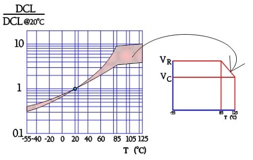
The peculiar break in the leakage current curve de-pends on the derating that takes effect at 85 °C and stop further increase of the leakage current in spite of in-creasing temperature.
DCL versus applied voltage
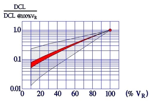
Reference: DCL at 100%VR.
The leakage current follows an almost linear dependence of the applied voltage – which should be the case if the dielectric acted as a pure resistor. The dielectric, however, is no pure resistor but a complicated oxide formation that together with the electrolyte and the base metal creates a valve function. Therefore the curve bends slightly downwards at lower voltages. If we compare with solid tantalums this characteristic is even more pronounced which has to do with the much larger margins to the formation voltage.
C 3.8.3 Failure modes
The most common failure mode is leakage of electrolyte through damaged glass-to-metal seals. The failure can be provoked by careless lead bending and, not the least, by temperature changes. It’s advisable to make sure that the manufacturer’s products can stand temperature changes.
C 3.8.4 Other wet electrolyte case sizes and styles
Surface-Mount
As the whole electronic component industry moved towards surface-mount technology, the wet tantalum capacitor had remained as an axial leaded device. The first early attempt to offer a surface-mountable wet tantalum capacitor was the Arcotronics SMTH. This was achieved by attaching special preformed SMD mounting tabs or terminations to the existing or standard axial tantalum case design. They could be manually soldered to the PCB using the tabs (see Figure C 3-73).
The next generation of surface-mountable wet tantalums was the M35 series, developed by Vishay. The M35 features a molded style with terminations. The design incorporates a complete T1 axial all-tantalum wet tantalum capacitor, which is welded to a lead frame, then molded (see Figure C 3-74).
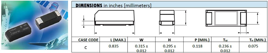
The latest addition by Vishay is the T22 series that is the first “true” SMD wet tantalum capacitor. It has a hermetically sealed rectangular tantalum case with terminations and is available in either bulk or a reel pack option (see Figure C 3-75 below).
High Energy
For high energy or bulk power applications, several axial wet tantalum capacitors are often connected in parallel and / or series. While customers can do this on their printed circuit board (PCB), the capacitor manufacturer can also provide a pre-assembled module or array of capacitors. The original arrays were made of the silver case capacitors, and there was actually a full MIL-PRF-3965 specification.
While these arrays are still available today, custom assemblies made from tantalum case wet tantalum capacitors available by more vendors such as Vishay, AVX, Exxelia. Example is a module that consists of wet tantalum case T1 capacitors on figure C 3-76 left.
wide variety of case materials and configurations to meet customer-specified performance requirements and are available with many termination options. Capacitor assemblies made include balancing resistors, diodes, and other components as needed to meet customer needs.
In some high energy or bulk power applications, the best solution may be the relatively new high energy, sometimes termed “hybrid,” wet tantalum capacitors. These capacitors utilize a tantalum anode and tantalum case, but need a hybrid cathode made by depositing a material such as ruthenium or palladium on a small piece of tantalum foil. These large case size wet tantalums reach capacitance values of over 72,000μF at 25V and are used in energy hold-up and pulse power applications.
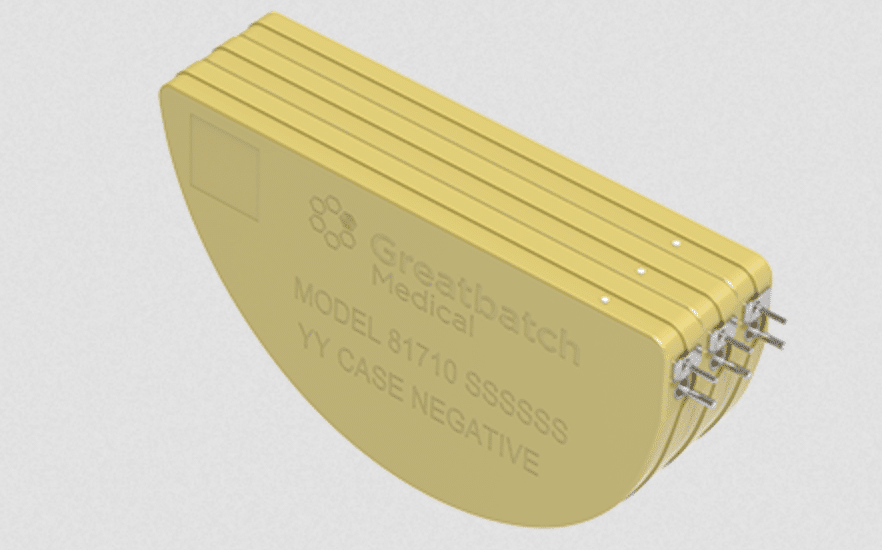
Very specialized designs, made with titanium cases, a special electrolyte, and rated for high voltages, have been used in medical implantable ICD applications for over 20 years. An individual ICD capacitor may provide 400μF at 250V in the relatively stable environment of the human body at an ambient temperature of 37ºC. See figure C-37.
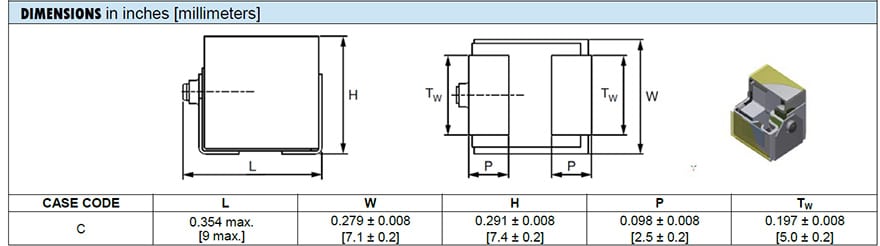
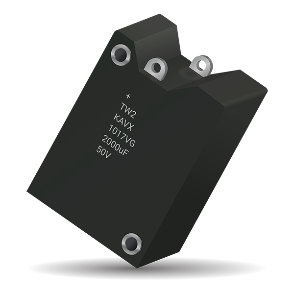
Military versions of the high energy “hybrid” capacitors were developed in various configurations with one or multiple anodes in a cylindrical/rounded square cases with radial terminations, such as illustrated on examples in Figure C 3-78 below.
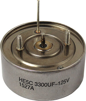
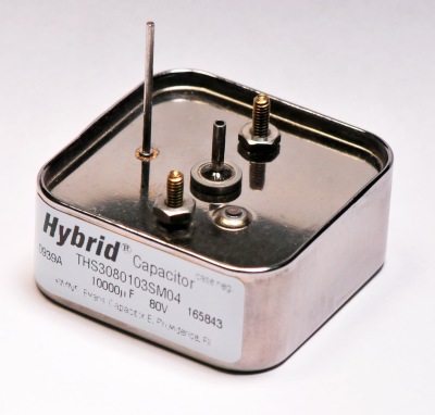
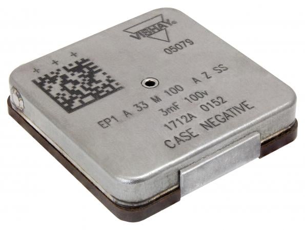
Figure C3-78 illustration of high energy tantalum wet capacitors