POLYESTER CAPACITORS PET / KT and MKT
C 2.3 POLYESTER CAPACITORS (PET)/ KT and MKT
Sometimes polyester capacitors are called Mylar. The abbreviation PET above comes from Poly Ethylene Terephtalate (also abbreviated PETP). On the pattern of European standards we use in this book the common abbreviations KT for film/foil design and MKT for metallized film. Otherwise we write en clair or with the summary abbreviation PET. As ´polyester´ also Poly Ethylene Naphtalate, PEN, is offered for sale. This material is dealt with separately under C2.7.3.
C 2.3.1 General comments to PET and PEN
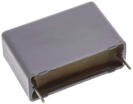
The polyester film is most reliable and together with PP most used of the plastic films. It can be produced in thicknesses down to 0.7 μm (0.03 mils). Its tensional stability is high and its εr ≈ 3.2. This has facilitated manufacture of one for organic dielectrics very space-saving capacitor. A typical field of application is decoupling. Certain applications like switched mode power supplies (SMPS) require for filtering and decoupling purposes large capacitance and moderate losses which have made the MKT capacitor an attractive replacement for the relatively expensive ceramic X7R capacitors. A common design may look like the one in Figure C2-34.
Furthermore the MKT capacitor can stand +125 °C. This has tempted a number of manufacturers to produce it in a chip design. But the mentioned heat conditioned shrinking in section C 2.1.7 is most pronounced in PET capacitors. This has led to many setbacks just for the SM types. Today mainly two different methods apply for preventing such heat rises during the soldering procedures that they release a detrimental shrinking.
- The components are supplied with such encapsulations and electrode designs that the heat penetration into the component is obstructed.
- The molecular memory of the initial location before the elongation is deleted in a heat and pressure process during manufacture.
Thus the risk of shrinking is reduced with the latter method which is restricted to stacked designs only. Therefore the dimensions could be held down with a minimum of encapsulation. Then, however, the heat penetration will be higher and at temperatures of 230 °C the film material is damaged. One solves in other words the shrinking problem but increases risk of serious material damage. Soldering methods and temperatures have to be chosen and supervised so that the chosen capacitor type can stand these processes. An infrared (IR) reflecting film and IR soldering seem for the moment to be the only way out as long as we deal with traditional PET films. The latest films are more resistive specified for 125 °C and can endure peak temperatures reaching 235 °C at reflow soldering. The film manufacturer has altered the thermo-mechanical properties to reduce shrinkage when used as a dielectric in SMD capacitors.
The shrinking effects are best controlled by ESR measurements at the resonance frequency before and after soldering; see C 2.1.6, Termination.
Advantages with PET
- Thin film with a high quality.
Disadvantages with PET
- The temperature dependence is comparatively large and non-linear.
- The dissipation factor is comparatively large, approximately 0.5% at 1 kHz.
- The material suffer from properties that in, for example, hi-fi applications (analogue technique) may give perceptible distortion.
Poly Ethylene Naphtalate (PEN) is a relative to polyester but somewhat more heat resistant. Capacitors with this dielectric often are presented under the title polyester. The material attracts the interest mostly for SMD designs. They are manufactured in stack technology with a film thickness of down to 1.5 μm (0.06 mils). According to some papers such chips are able to stand up to both wave and IR soldering but only IR and vapor phase soldering is recommended. However, recent developments and film improvements indicate a considerable step upwards in the temperature range. With a derating of the applied operating voltage above 125 °C an upper temperature of + 150°C is quite possible.
The material is still too expensive to be used on a large scale.
- Capacitance 1 nF… 10 μF.
- Tolerance ±5% and ±10%.
- Temperature range -55/+125°C (+150 °C).
- Rated voltage 16…400 V DC.
- Tanδ , 1kHz, 20°C, ≈ 0.4…0.5% (≤0,8%).
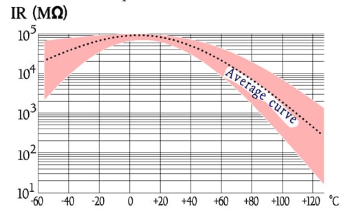
- IR, 20°C, ”typical” 30 000 s; ≥1 GΩ or ≥ 400 s.
- Stability ΔC/C ≤5%.
- TC ≈ +220±10ppm/°C (average over the temperature range).
- εr ≈ 3.2.
- Dielectric absorption ≈ 0.15 %.
- Recommended derating 0.6xVR.
C 2.3.2 Temperature and frequency dependencies
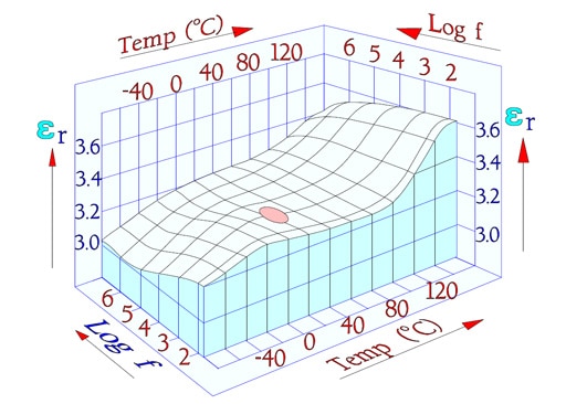
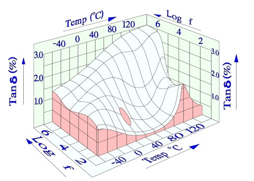
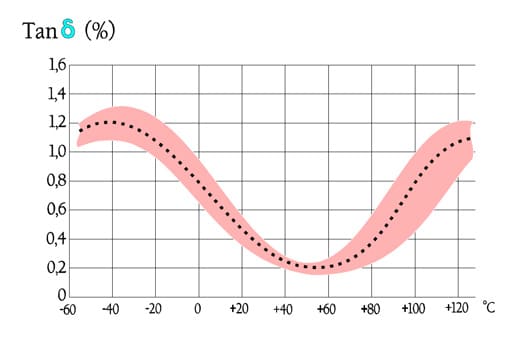
We will start with two three-dimensional diagrams that show how εr (and with that C) and Tanδ (DF) change with frequency and temperature. Specified measurement points have been inserted as ovals in the diagrams (Figure C 2-35 and –36).
The diagrams are interesting because they show how temperature and frequency rule the parameters in a complicated manner, especially Tanδ .
The following diagrams are more common and easy to interpret. In some of them there are curves inserted for a PEN, i.e., Poly Ethylene Naphtalate. It is comparatively more temperature resistant than PET and for that reason used in SMD types.
Among the curves over the frequency dependencies of impedance there are shown typical resonance frequency ranges. Because there are comparatively small changes of capacitance and the losses are rather small impedance diagrams get a pliable bend downwards into a sharp tip around the resonance frequency. Examples of resonance frequencies are shown in Figure C2-42.
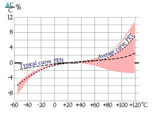
The temperature dependence of capacitance is influenced also by its magnitude, by the dielectric thickness and the design of the winding. This is reflected in the distribution at higher temperatures.
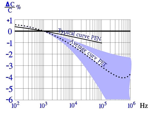
The frequency dependence of capacitance is ruled not only by the material but, to some extent, also by its magnitude and capacitor construction (foil or metallized design). Sometimes there are shown examples of series capacitance measurements according to Formula C1-10 where an apparent increase occurs at higher frequencies. This increase is hinted by the dotted line in Figure C2-38.
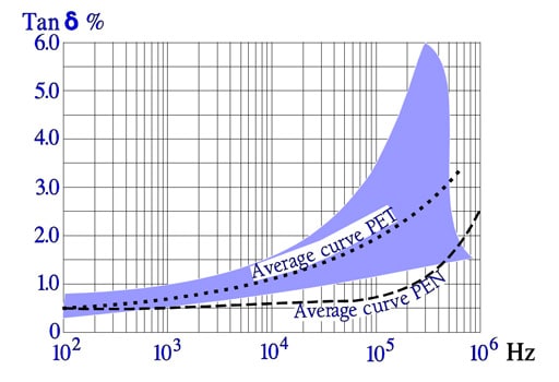
Also the frequency dependence of losses is ruled by the capacitance magnitude and by the design. While the dotted curve may represent a metallized design (MKT) in the magnitude of some hundred nF the foil capacitor (KT) is localized in the lower part of the curve area.
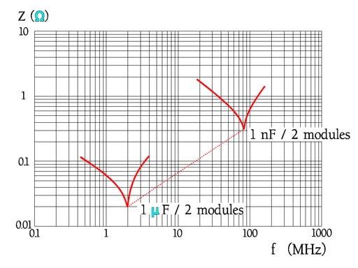
Other manufactures and other module distances give other resonance frequencies. Always check with the manufacturers’ data sheet.
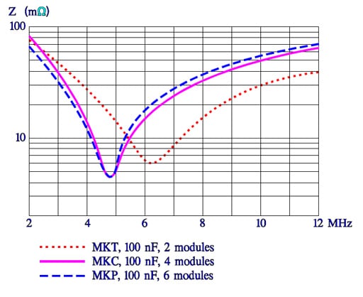
The seemingly sharp points in the impedance curve look in another magnification somewhat more round. Figure C2-43 shows results from measurements of MKT, MKC and MKP capacitors, 100nF. The slightly lower losses for MKC and MKP capacitors is shown as a lower ESR.
C 2.3.3 Failure modes
Bump, vibration and temperature cycling may in, above all hermetic cans, cause interruption in internal termination leads or in the connecting link terminal lead – spray metal compound – metallizing. Types that are molded into epoxy run less risk. If the casing on the other hand consists of plastic humidity will diffuse into the component. Humidity, however, impairs primarily only in the state of liquid (for example at a condensation) which will cause electrolysis, especially in the presence of a DC load. Thus non-hermetic components of this type or SMD design can bear a high RH, at least for 1000 hrs. If we can accept a C of +3 to +5% (εr for water approximately 80) and a decreasing IR there is no harm done. When the moisture content outside of the component decreases the humidity diffuses out of the winding and the capacitance increase goes back. If the component on the other hand operates in a jungle climate for months the IR will decrease until the leakage current starts electrolysis in the metallization. It will end in an open circuit.
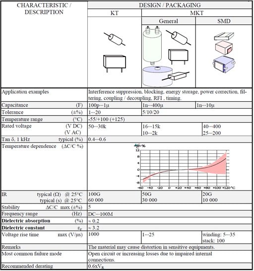
Table C 2-4. POLYESTER (PET) / MYLAR / KT / MKT